


Quick Research
Generate reliable direction feasibility study reports for your R&D in just a few steps.

Technical Q&A
Discover and master advanced knowledge NOW. Basics, ideas, possibilities, all at once.

Find Solutions
As an expert in R&D theories, this can generate solutions to your technical problems instantly.

Evaluate Feasibility
Analyze your overall solution with one click, know your potential R&D risks in advance.

Monitor Landscape
Get weekly tech updates, stay abreast of the latest tech innovations and key insights.
Variable aperture structure, camera module and electronic device
A camera module and aperture technology, which is applied to branch equipment, telephone structure, television and other directions, can solve the problems of complex structure of variable aperture, complicated rotation and rotation, magnetic interference of motor, etc., and achieves simple preparation method and control method, simple structure and high structure. Small size, high image quality effect
- Summary
- Abstract
- Description
- Claims
- Application Information
AI Technical Summary
Problems solved by technology
Method used
Image

Examples
Embodiment 1
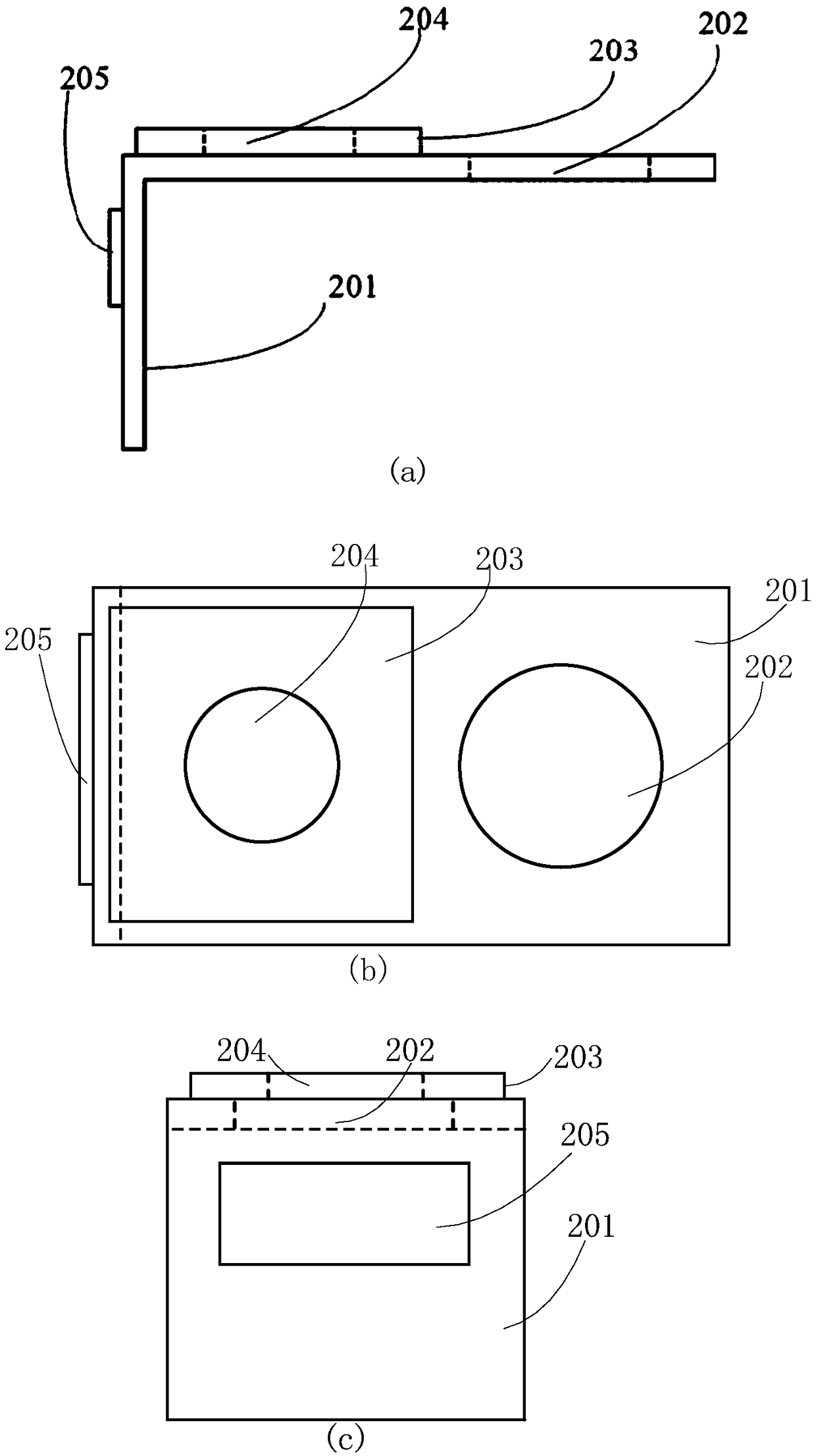
[0066] like figure 2 As shown, the variable aperture structure provided by Embodiment 1 includes an aperture carrier 201 , a lens aperture 202 , an aperture moving structure 203 , an aperture hole 204 and a driver 205 . in:
[0067] The aperture carrier 201 includes a horizontal portion and a vertical portion fixed vertically to each other, and the aperture carrier in this embodiment may also be an n-shaped structure composed of two vertical portions and one horizontal portion. In application, the horizontal part of the aperture carrier 201 is placed above the lens of the camera module, and the vertical part is connected to the lens of the camera module, the motor or the side of the motor housing.
[0068] The lens light hole 202 is provided on the horizontal part of the aperture carrier 201 at the end away from the vertical part, and its size is equal to or larger than the light hole of the lens, as long as the lens light hole does not affect the light passing amount of the...
Embodiment 2
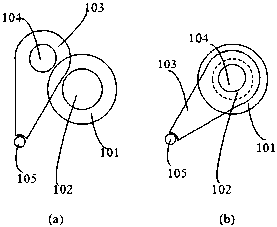
[0080] The variable aperture structure provided by embodiment 2 is as Figure 8 As shown, it includes an aperture carrier 801 , a lens aperture 802 , an aperture moving structure 803 , an aperture hole 804 , and a driver 1105 . Specifically, the aperture carrier 801 includes a horizontal portion and a vertical portion that are vertically fixed to each other. The lens aperture 802 is opened on the horizontal portion of the aperture carrier 801 at the edge away from the vertical portion. The diameter of the lens aperture 802 is the same as that of the horizontal portion. Align the edges. The aperture moving structure 803 can be a rectangular plate, and the aperture hole 804 is opened on the upper edge of the aperture moving structure 803. The diameter of the aperture hole 804 is aligned with the edge of the aperture moving structure 803, and the aperture moving structure 803 is movably installed on the aperture carrier 801. Driven by the driver 805, it moves to the lens light h...
Embodiment 3
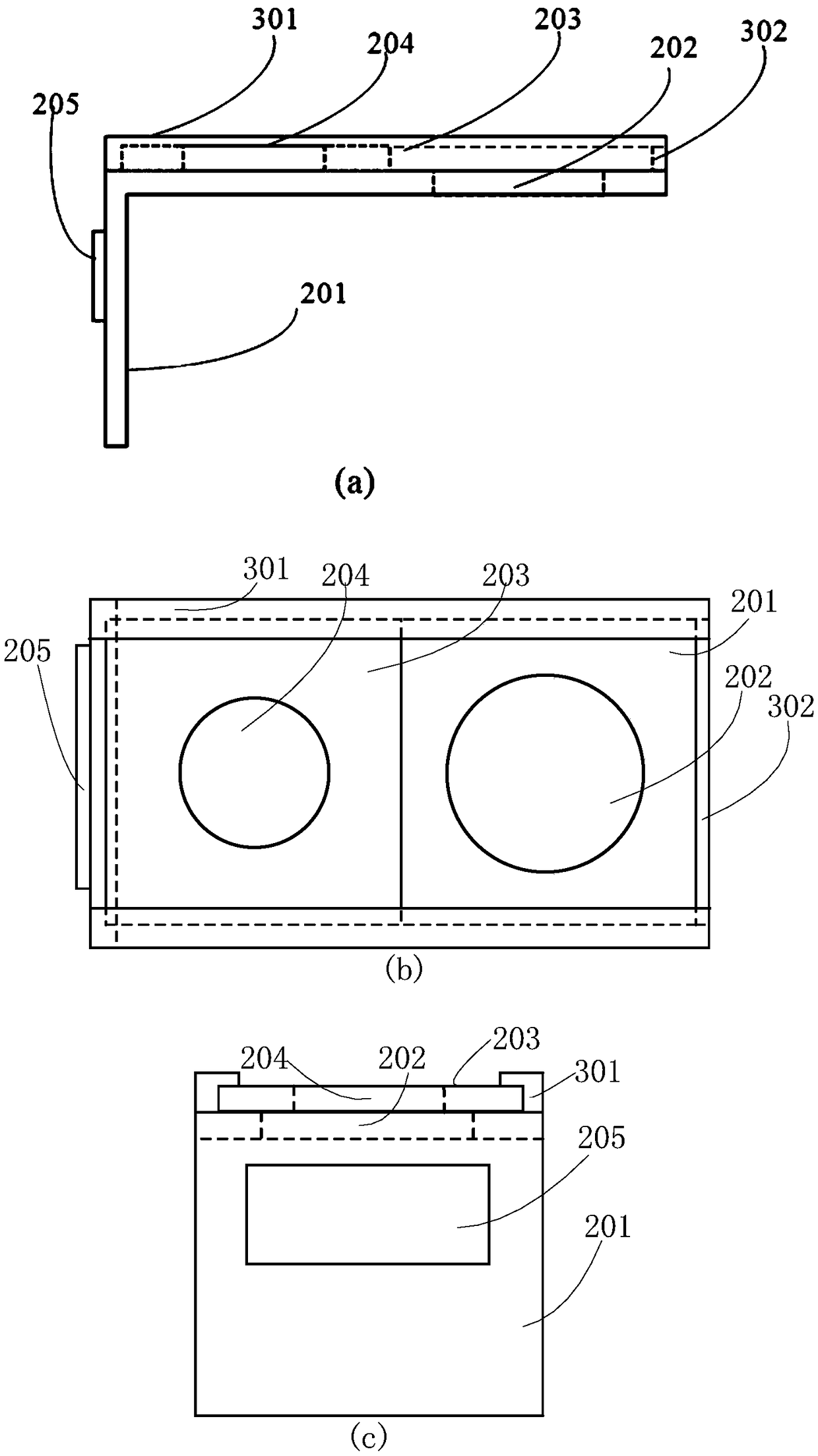
[0085] The variable aperture structure provided by embodiment 3 is as Figure 11 As shown, it includes an aperture carrier 1101 , a lens aperture 1102 , a first aperture moving structure 1103 , a first aperture hole 1104 , a second aperture moving structure 1106 , a second aperture hole 1107 , a first driver 1105 and a second driver 1108 . in:
[0086] Aperture carrier 1101 includes an inverted L-shaped horizontal part and two vertical parts, the two vertical parts vertically connect the two ends of the L-shaped horizontal part, and a lens aperture 1102 is opened at the corner of the inverted L-shaped horizontal part. The horizontal part of the aperture carrier 1101 is placed on the lens of the camera module, and the vertical part is attached to the lens of the camera module, the motor or the side of the motor housing.
[0087] The first aperture moving structure 1103 can be a rectangular plate, which is arranged on an arm of the horizontal part of the aperture carrier 1101, ...
PUM
 Abstract
Description
Claims
Application Information
 - R&D Engineer
- R&D Manager
- IP Professional
- Industry Leading Data Capabilities
- Powerful AI technology
- Patent DNA Extraction
Browse by: Latest US Patents, China's latest patents, Technical Efficacy Thesaurus, Application Domain, Technology Topic, Popular Technical Reports.
© 2024 PatSnap. All rights reserved.Legal|Privacy policy|Modern Slavery Act Transparency Statement|Sitemap|About US| Contact US: help@patsnap.com