
High-speed mixer

A high-speed mixer and machine body technology, applied in the direction of mixers, mixers with rotating stirring devices, mixer accessories, etc., can solve the problems of material waste, dust pollution, accelerated physical changes, etc., to achieve fast and comprehensive opening, reduce labor, The effect of reducing waste

Pending Publication Date: 2018-11-13
YANCHENG SHENYUAN PLASTIC
View PDF0 Cites 0 Cited by
  • Summary
  • Abstract
  • Description
  • Claims
  • Application Information

AI Technical Summary

Problems solved by technology

[0002] A mixer is a mechanical device that uses mechanical force and gravity to uniformly mix two or more materials; in the process of mixing, it can increase the contact surface area of ​​materials to promote chemical reactions and accelerate physical changes; When mixing materials, most of them realize the mixing and processing of granular or powdery materials. In the feeding process of general mixers, the woven bag containing granular powder is usually directly lifted and inverted on the inlet of the mixer. At the feed port, that is, the discharge port of the woven bag is connected with the feed port of the mixer, so that the granular powder material is poured from the woven bag into the mixer; in this process, not only the staff needs to control the woven bag at all times, To prevent the falling of the woven bag, and the inconsistency between the discharge port of the woven bag and the feed port of the mixer, etc. There is a large gap between them. During the process of pouring the granular powder material from the woven bag into the mixer, a large amount of granular powder will fall to the outside of the outlet of the mixer, which will not only cause material waste, but also cause dust. Pollution

Method used


Image

  • High-speed mixer
  • High-speed mixer
  • High-speed mixer

Examples


Embodiment 1

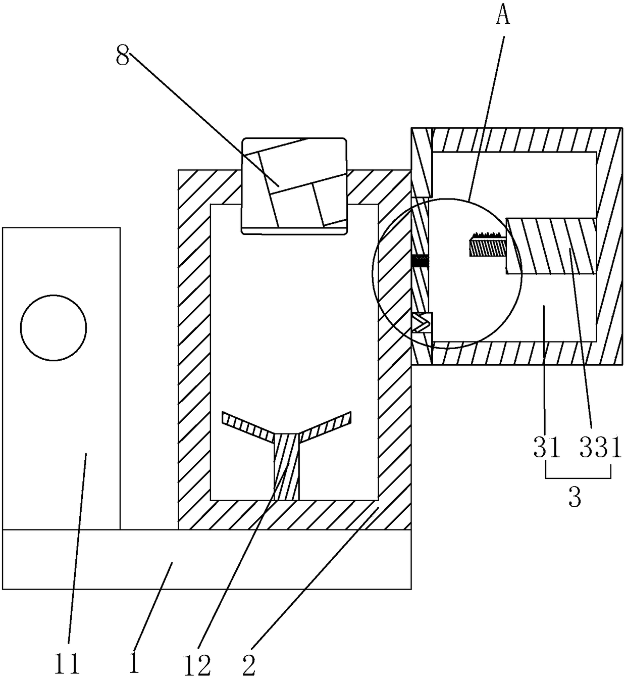
[0035] Embodiment 1: a kind of high-speed mixer, such as figure 1 As shown, it includes a body 1 and a power control unit 11. The body 1 is provided with a cylinder 2 for storing materials and performing mixing work. The upper end of the cylinder 2 is provided with a feeding port 21 communicating with the inside of the cylinder 2. The interior of the cylinder 2 is provided with a stirring blade 12 driven by a power control unit 11; the material enters the cylinder 2 through the feeding port 21, and the stirring blade 12 rotates in the cylinder 2 under the control of the power control unit 11 to realize the mixing of the material. The stirring mix works.

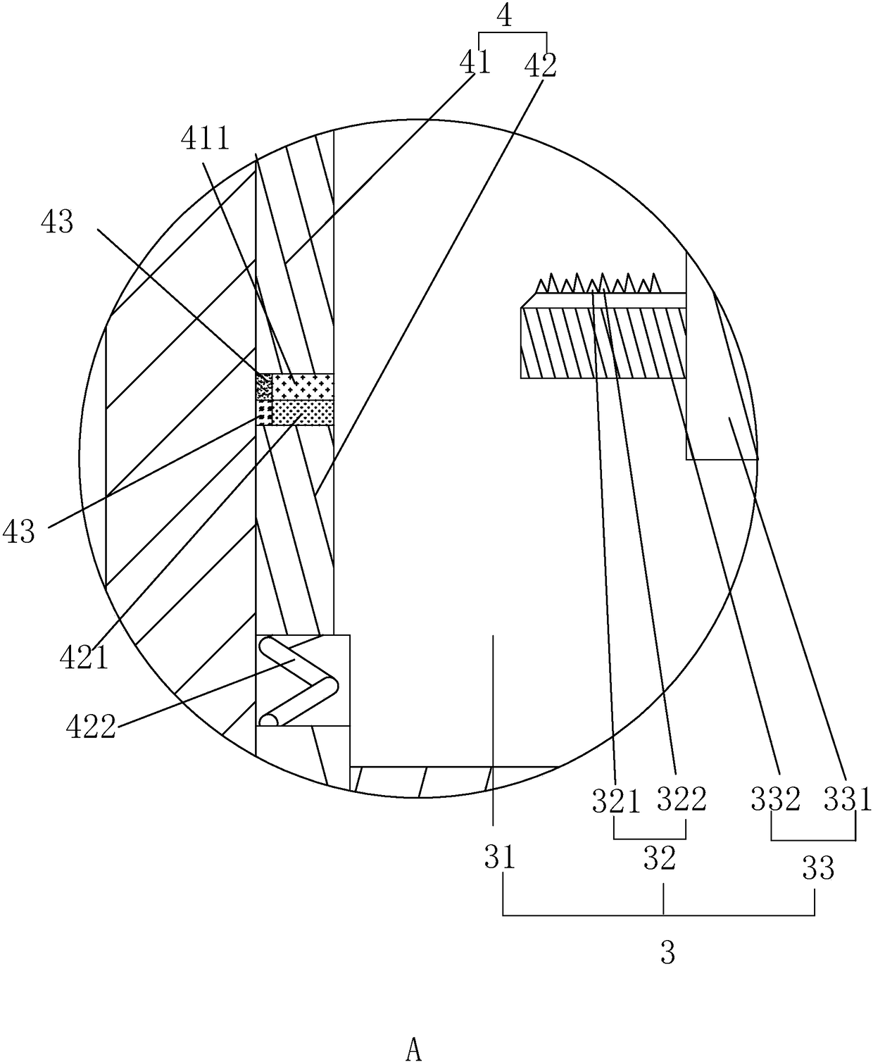
[0036] Such as figure 1 and 2As shown, at this time, an unsealing device 3 connected to the cylinder 2 is provided on the body 1 near the cylinder 2. The unsealing device 3 includes a working chamber 31 connected to the side wall of the cylinder 2. There is a power mechanism 33, that is, a drive cylinder 331 is fixedly con...

specific Embodiment approach

[0037] Specific implementation method: the woven bag 8 with the material is directly placed at the feeding port 21, and the woven bag 8 is embedded in the feeding port 21 under the gravity of the internal material, and the bottom of the woven bag 8 has a penetrating feeding port 21 to enter The part inside the cylinder body 2, at this time, the woven bag 8 has realized the sealing of the feeding port 21; the control electromagnet 1 411 and the electromagnet 2 421 are energized, and under the mutual repulsion of the two electromagnets, the upper door panel 41 is upward. Sliding, the lower door panel 42 slides downwards, and the compression spring 422 is completely compressed, at this time, the door body 4 is in an open state, that is, the communication between the working chamber 31 and the inside of the cylinder body 2 is realized; the driving cylinder 331 is controlled to work, and the piston rod 332 protrudes from the driving cylinder 331, and the process of the piston rod 33...

Embodiment 2

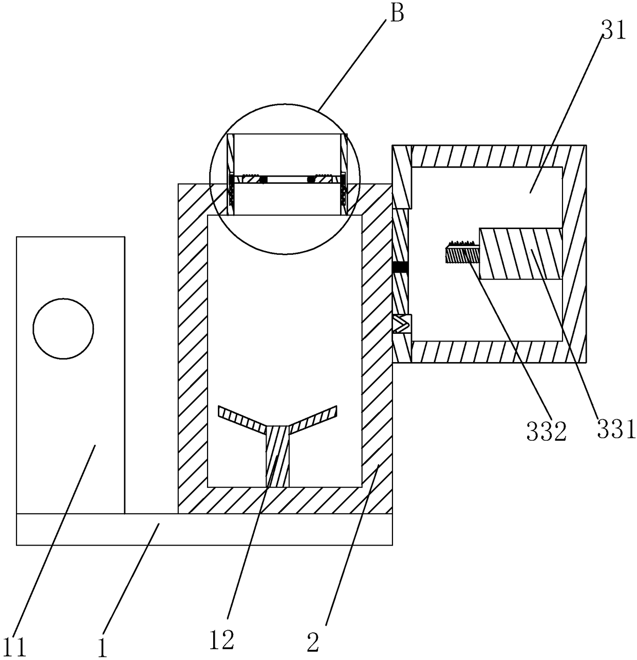
[0042] Embodiment 2: a kind of high-speed mixer, the difference with embodiment 1 is, as image 3 and 4 As shown, an outwardly extending protective rib 5 is provided at the feeding port 21; The outer peripheral wall of the support plate 61 is fixedly connected with a connection block 62, and the inner wall of the protective rib 5 is provided with a plurality of track grooves 63. There is a buffer spring 64, and the end of the buffer spring 64 away from the connecting block 62 is connected and fixed to the inner wall of the protective rib 5; a through hole 611 communicated with the feeding port 21 is provided at the support plate 61 near the middle position; and it rotates on the support plate 61 A blanking plate 7 is connected, and a plurality of protrusions 71 are arranged on the upper surface of the blanking plate 7 .

[0043] Specific implementation method: under the effect of protective rib 5, can make the woven bag 8 that material is housed in protective rib 5, at this ...


PUM


Abstract

The invention discloses a high-speed mixer, comprising a body. The body is provided with a barrel for storing materials and mixing the materials; the upper end of the barrel is provided with a feed port communicated with the inside of the barrel; the part of the body close to the barrel is provided with an unblocking device connected with the barrel; the unblocking device includes a working chamber connected with the sidewall of the barrel; a blade is slidably connected inside the working chamber and can horizontally slide in the working chamber; a door that controls the working chamber and the barrel to internally open or close is arranged in the working chamber; electromagnet I controlled by a circuit signal is fixed to the bottom of the door; electromagnet II that repels the electromagnet I is fixed right under the door in the working chamber. The high-speed mixer has the advantages that material waste can be effectively reduced and pollution of surrounding air due to powdery materials can be effectively decreased.

Description

technical field [0001] The invention relates to the field of material mixing equipment, in particular to a high-speed mixer. Background technique [0002] A mixer is a mechanical device that uses mechanical force and gravity to uniformly mix two or more materials; in the process of mixing, it can increase the contact surface area of ​​materials to promote chemical reactions and accelerate physical changes; When mixing materials, most of them realize the mixing and processing of granular or powdery materials. In the feeding process of general mixers, the woven bag containing granular powder is usually directly lifted and inverted on the inlet of the mixer. At the feed port, that is, the discharge port of the woven bag is connected with the feed port of the mixer, so that the granular powder material is poured from the woven bag into the mixer; in this process, not only the staff needs to control the woven bag at all times, To prevent the falling of the woven bag, and the inc...

Claims


Application Information

Patent Timeline
IPC IPC(8): B01F7/18B01F15/02
CPCB01F27/90B01F35/7131
Inventor 袁森吴航贺盟唐家烨柏爱华
Owner YANCHENG SHENYUAN PLASTIC
Learn More