
Drilling device

A drilling device and frame technology, which is applied in metal processing machinery parts, maintenance and safety accessories, metal processing equipment, etc., can solve the problem that the flow of cutting fluid cannot be changed or adjusted.

Inactive Publication Date: 2018-11-13
CHONGQING YOUBO MACHINERY MFG
View PDF0 Cites 11 Cited by
  • Summary
  • Abstract
  • Description
  • Claims
  • Application Information

AI Technical Summary

Problems solved by technology

[0004] The present invention intends to provide a drilling device to solve the problem in the prior art that the cutting fluid is used to cool down the drill bit, the flow rate of the cutting fluid cannot be changed and cannot be adjusted according to the change of the drill bit speed

Method used


Image

  • Drilling device
  • Drilling device

Examples


Embodiment

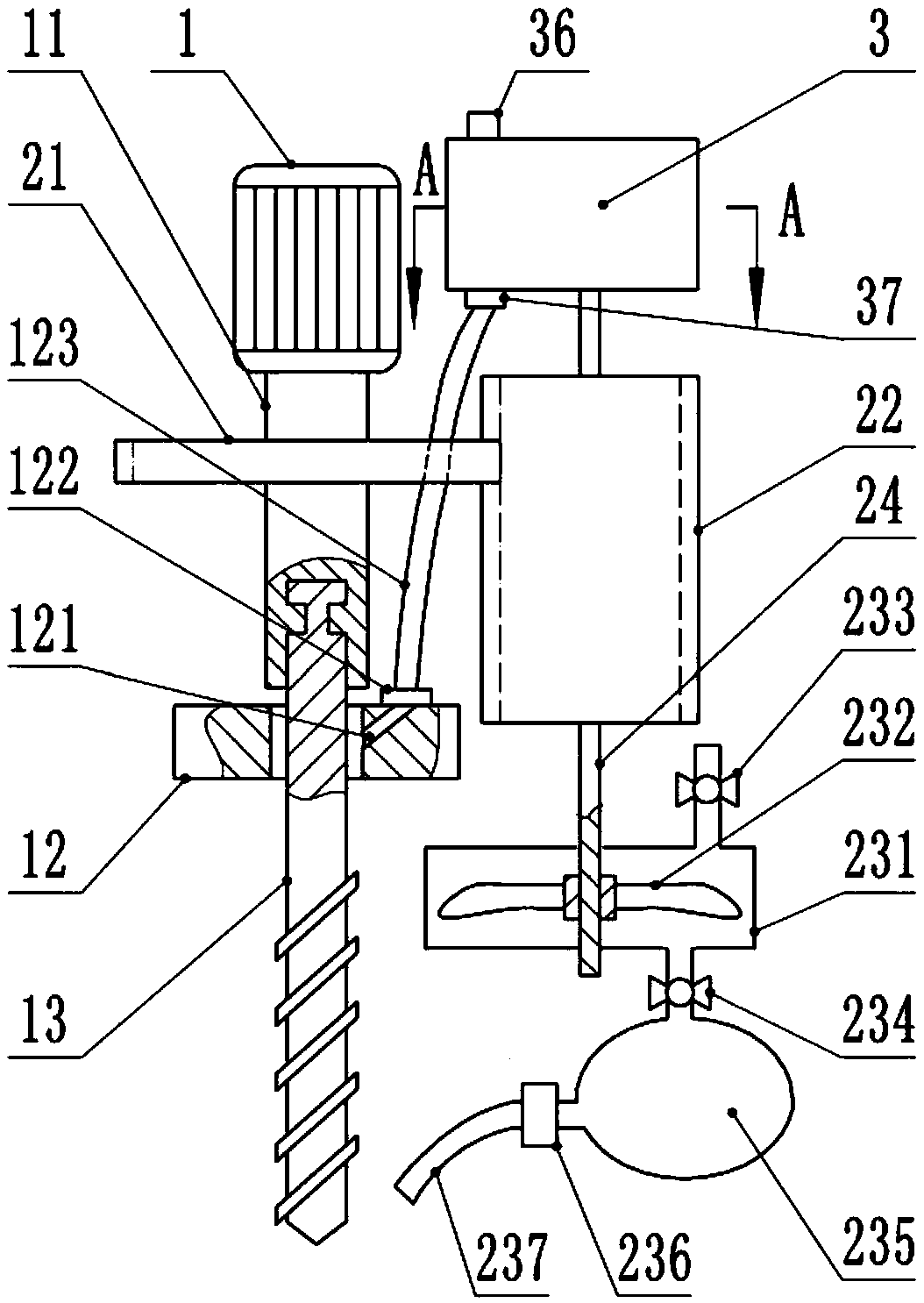
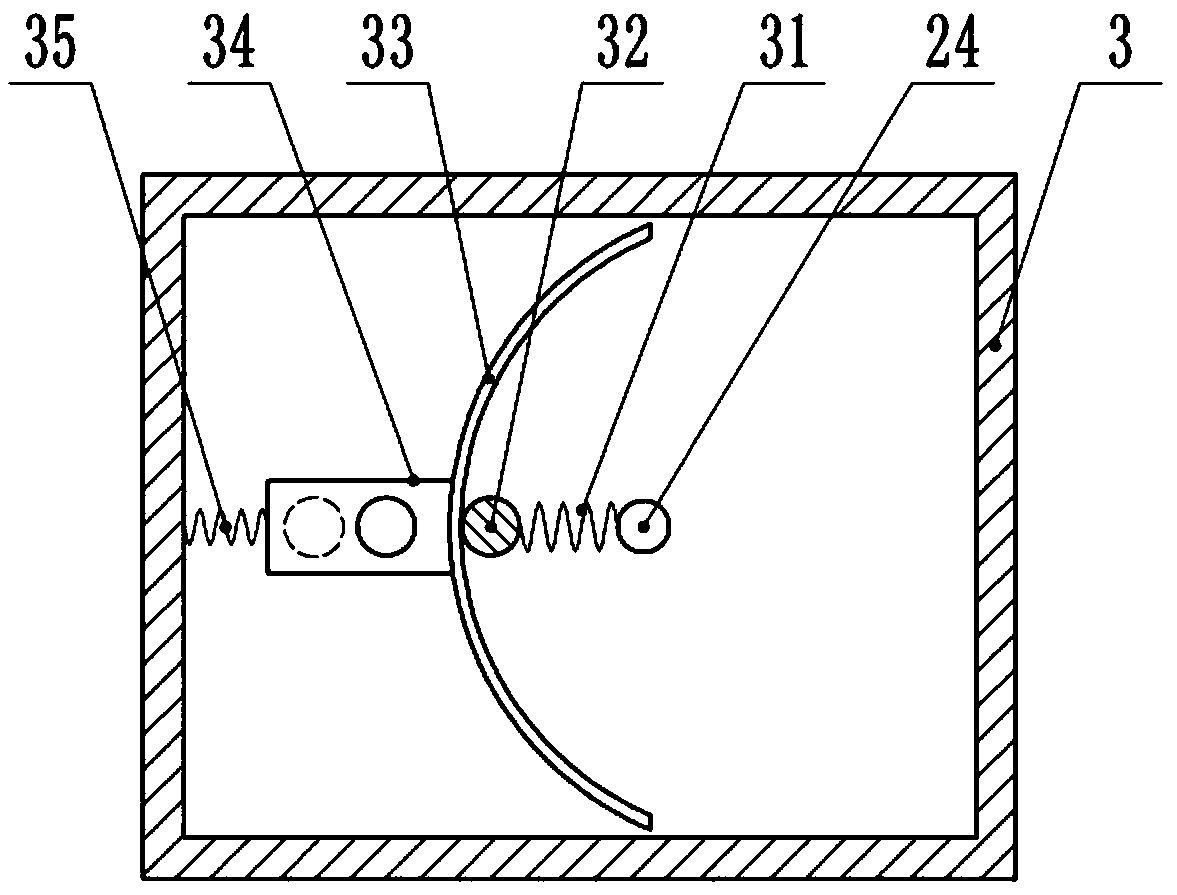
[0021] Such as figure 1 , figure 2 Shown: a drilling device, including a frame, a connecting block 12 and a motor 1 vertically slidably connected to the frame, the output shaft of the motor 1 is coaxially connected with a first rotating shaft 11, and the lower part of the first rotating shaft 11 A drill bit 13 is coaxially connected, and the outer wall of the drill bit 13 is provided with a spiral guide groove; the connecting block 12 is slidably connected on the frame, and a through hole is provided on the connecting block 12, and the upper part of the drill bit 13 is rotatably connected to the connecting block 12 in the through hole. The middle part of the first rotating shaft 11 is coaxially connected with a driving gear 21, and the driving gear 21 is meshed with a driven gear 22. The thickness of the driven gear 22 is greater than the thickness of the driving gear 21, so that when the drill bit 13 drills and moves downward, the driving gear 21 Still can mesh with driven...


PUM


Abstract

The invention relates to the technical field of drilling machining and discloses a drilling device. The drilling device comprises a drill bit and a driving gear connected with the drill bit coaxially.The driving gear is meshed with a driven gear. A liquid box is arranged above the driven gear. A liquid outlet is formed in the liquid box. A stop block for opening or closing the liquid outlet is arranged in the liquid box. The stop block is provided with an outlet. The outlet and the liquid outlet are arranged in a staggered manner. A compression spring is fixedly connected between the stop block and the inner wall of the liquid box. A second rotating shaft is connected in the liquid box in a rotating manner. The second rotating shaft and the driven gear are connected coaxially. The secondrotating shaft is fixedly connected with a tension spring. A gravity ball is fixedly connected to the other end of the tension spring. The gravity ball abuts against an arc-shaped block intermittently. According to the drilling device, along with the change of rotating speed of the drill bit, the centrifugal force borne by the gravity ball changes, thus the size of the opening degree of the liquidoutlet of the liquid box is adjusted, the flow amount of cutting fluid can be adjusted automatically according to the rotating speed of the drill bit, and the situation that when the speed of the drill bit is low, too much cutting fluid flows out, and waste is caused is avoided.

Description

technical field [0001] The invention relates to the field of drilling technology, in particular to a drilling device. Background technique [0002] Drilling refers to the operation of machining a hole in a solid material with a drill bit. There are many ways of drilling, including geological drilling, mechanical drilling and so on. Among them, mechanical drilling is widely used in the drilling of various process holes or assembly holes on hard metal plates, casting blanks, finished parts, etc. (hereinafter referred to as workpieces). During the drilling process, due to the friction between the drill bit and the workpiece , resulting in a large amount of heat. A large amount of heat will cause certain damage to the drill bit, and it is easy to cause the drill bit to break; in order to avoid the breakage of the drill bit, the existing method is to use cutting fluid to cool the drill bit. [0003] Due to the different rotating speeds of drills required in the drilling proces...

Claims


Application Information

Patent Timeline
Patent Type & Authority Applications(China)
IPC IPC(8): B23Q11/10
CPCB23Q11/10
Inventor 陈明友
Owner CHONGQING YOUBO MACHINERY MFG
Learn More