Serial robot kinematics parameter calibration method based on vision

A technology of robot kinematics and kinematic parameters, applied in the field of robot calibration, can solve the problems of complex, high technical requirements of installation, debugging and measurement process, expensive calibration process of measuring instruments, etc., and achieve the effect of improving absolute positioning accuracy and low cost.

Active Publication Date: 2018-11-13
HARBIN ENG UNIV
View PDF6 Cites 21 Cited by
  • Summary
  • Abstract
  • Description
  • Claims
  • Application Information

AI Technical Summary

Problems solved by technology

[0003] Usually, high-precision measuring equipment is used in the robot calibration algorithm to measure the actual pose of the robot end, but such measuring instruments are very expensive and the calibration process is very complicated, which requires high technical requirements for installation, debugging and measurement process

Method used


Image

  • Serial robot kinematics parameter calibration method based on vision
  • Serial robot kinematics parameter calibration method based on vision
  • Serial robot kinematics parameter calibration method based on vision

Examples


specific Embodiment

[0062] (1) Establish a kinematic error model

[0063] Define the connecting rod parameter vector as: vector of parameters for the link approximately parallel to the previous joint axis Parameter vectors for other linkages Among them, a i , d i ,α i ,θ i ,β i are the kinematic parameters of the i-th (i=1, 2, 3, 4, 5, 6) connecting rod, which are respectively the connecting rod length, connecting rod offset, connecting rod rotation angle, joint angle and connecting rod parallel to the joint axis corner.

[0064] Assume that the actual kinematic parameter vector of the robot is Its nominal value is Kinematic parameter error vector Based on the improved DH model, the robot kinematics error model can be obtained:

[0065]

[0066] Among them, ΔP e and ΔR e represent the tiny translation and rotation errors at the end of the robot, respectively, with are the error Jacobian matrices with respect to position and attitude, respectively.

[0067] Define the kt...


PUM


Abstract

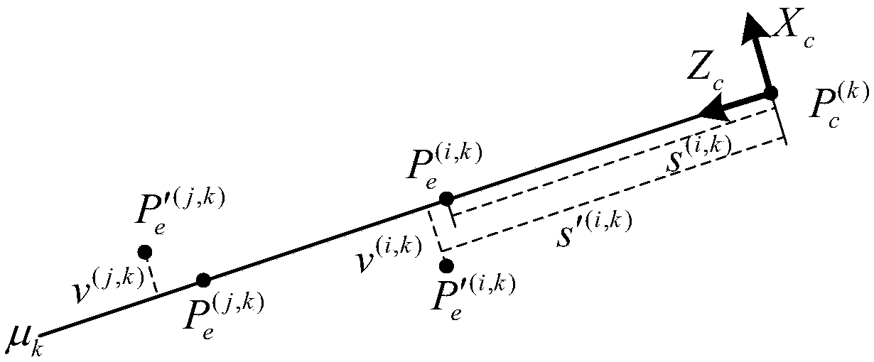
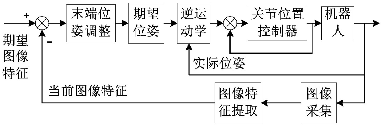
The invention provides a serial robot kinematics parameter calibration method based on vision. The optical axis of a camera serves as virtual straight line constraint, and a kinematics error model based on straight line constraint is built; a fixed point is selected from a calibration plate fixed to the tail end of a robot to serve as a feature point, motion of a mechanical arm is controlled through a visual control method based on images, and the feature point is made to arrive at the optical axis; according to joint angular data of the robot, the forward kinematics is used for calculating the nominal position of the feature point and the alignment error matrix; and the kinematics parameter error is estimated through the iterative least squares algorithm, and the actual kinematics parameter is calculated according to the nominal kinematics parameter. According to the serial robot kinematics parameter calibration method based on vision, the optical axis of the camera serves as virtualconstraint, calibration can be completed through only the joint angular data of the robot, the cost is low, operation is easy, expensive high-precision measuring equipment is not needed, and the method has the universality for serial robot calibration and can be widely applied to industrial, space and underwater environments to improve the absolute positioning precision of the mechanical arm.

Description

technical field [0001] The invention relates to a vision-based calibrating method for kinematics parameters of serial robots, belonging to the field of robot calibrating. Background technique [0002] As robots are more and more used in tasks such as assembly, surgery, and collaboration, there are increasingly higher requirements for the positioning accuracy of the robot's end. At present, the position and attitude errors of the robot end cannot be directly measured, and are usually calculated indirectly by using kinematic models and joint angle data. Due to the influence of manufacturing tolerances, wear, transmission errors, installation position, environmental changes and other factors, there are deviations between the actual kinematic parameters in the robot model and their nominal values. If the nominal kinematic parameters are used to calculate the end pose of the robot, it will lead to The absolute localization accuracy of the end pose is reduced. In order to improv...

Claims


Application Information

Patent Timeline
Patent Type & Authority Applications(China)
IPC IPC(8): B25J9/16
CPCB25J9/1605B25J9/1697
Inventor 朱齐丹谢心如李超夏桂华张智蔡成涛吕晓龙刘志林
Owner HARBIN ENG UNIV
Why Eureka
Try Eureka