
Integrated structure of electronic power control power system for electric vehicle

A technology of electronic power and power system, applied in the direction of electric power unit, arrangement of cooling combination of power unit, control device, etc., can solve the problems of large number and length of cables, high structural cost, complicated installation, etc., and improve space utilization The effect of improving the efficiency, improving the integration of equipment, and simplifying the connection mode

Inactive Publication Date: 2018-11-13
SANMENXIA SUDA TRANSPORTATION ENERGY SAVING TECH
View PDF4 Cites 2 Cited by
  • Summary
  • Abstract
  • Description
  • Claims
  • Application Information

AI Technical Summary

Problems solved by technology

It takes up a lot of space in the car, the structure is complex, the layout is difficult, a large number of cables are exposed, the structure cost is high, the volume is large, the installation is complicated and difficult to repair, and the structure placed inside the car body is not compact enough
[0003] The existing motor and reducer are composed of two independent structures, not only the number of parts is large, but also the occupied space and weight will increase correspondingly, which is not conducive to the weight reduction of the whole vehicle and the improvement of the level of vehicle integration
[0004] Existing electronic power controllers are generally independent of the motor, and the number of cables used to connect the two is large and long, resulting in a lot of space waste and difficult maintenance

Method used


Image

  • Integrated structure of electronic power control power system for electric vehicle
  • Integrated structure of electronic power control power system for electric vehicle
  • Integrated structure of electronic power control power system for electric vehicle

Examples


Embodiment Construction

[0022] The present invention will be further described below in conjunction with the accompanying drawings and embodiments.

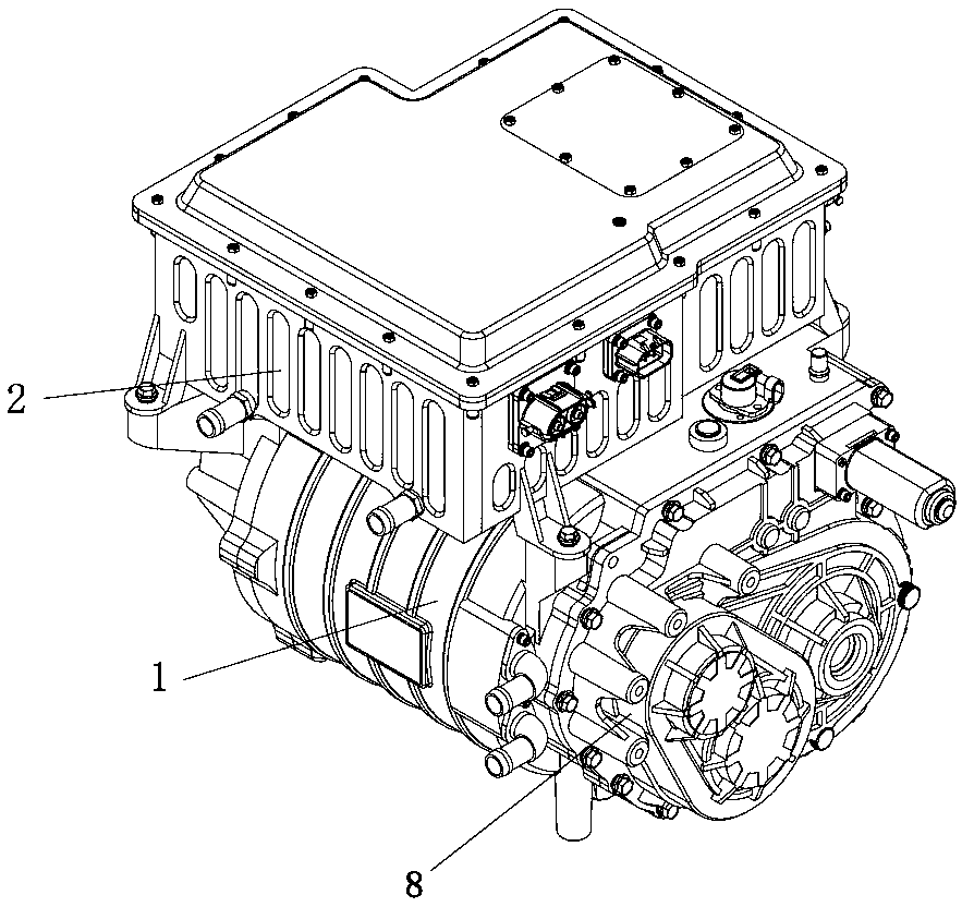
[0023] Such as figure 1 As shown, the present invention provides an integrated structure of electronic power control power system for electric vehicles, including a drive motor 1, a speed reducer 8 and an electronic power controller 2, wherein the speed reducer 8 is fixed on the output of the motor shaft of the drive motor 1 At the end, the electronic power controller 2 is fixed above the drive motor 1 .

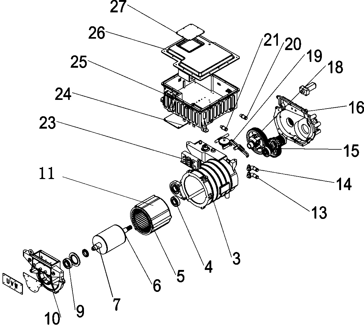
[0024] Such as figure 2 As shown, the drive motor 1 in the present invention is made up of a casing 3 and an inner layer cavity 11, and the inner surface of the casing 3 is provided with a keyway that can cooperate with the protrusion on the outer surface of the inner layer cavity 1 to prevent the casing from Relative sliding occurs between inner cavities. A stator 5, a rotor 6 and a motor shaft 7 are installed in the inner cavity 11, the motor sh...


PUM


Abstract

The invention discloses an integrated structure of an electronic power control power system for an electric vehicle. The integrated structure of the electronic power control power system comprises a driving motor, a speed reducer and an electronic power controller. The speed reducer is fixed to the output end of the driving motor, and the electronic power controller is fixed above the driving motor. The integrated structure of the electronic power control power system effectively reduces the size of a device, improves the integration degree of the device, integrates the connection of the driving motor and the speed reducer integrally, and simplifies the connection mode of the driving motor and the electronic power controller. In the space layout of the whole vehicle, the space utilizationrate of the electronic power control power system is improved, meanwhile, the processing cost of the product structure is reduced, and a complete and simple integrated structure of the electronic power control power system for the electric vehicle is provided for the whole vehicle; and specific lightweight design reduces the volume weight and processing cost of an electronic power control power device, and the integrated structure of the electronic power control power system can be more convenient and efficient in vehicle assembly.

Description

technical field [0001] The invention belongs to the field of electric vehicles, and in particular relates to an integrated structure of an electronic power control power system for an electric vehicle. Background technique [0002] Existing electric vehicle motors, reducers, and electronic power controllers are generally arranged separately. It takes up a lot of space in the car, the structure is complex, the layout is difficult, a large number of cables are exposed, the structure cost is high, the volume is large, the installation is complicated and difficult to overhaul, and the structure placed inside the car body is not compact enough. [0003] The existing motor and reducer are composed of two independent structures. Not only the number of parts is large, but also the occupied space and weight will increase correspondingly, which is not conducive to the weight reduction of the whole vehicle and the improvement of the level of vehicle integration. [0004] Existing elec...

Claims


Application Information

Patent Timeline
Patent Type & Authority Applications(China)
IPC IPC(8): B60K1/00B60K17/04B60K11/02
CPCB60K1/00B60K11/02B60K17/04
Inventor 李雪峰马科杜克强
Owner SANMENXIA SUDA TRANSPORTATION ENERGY SAVING TECH
Learn More