Ceiling face and wall face putty scraping device with automatic supplying and residual slurry automatic recovery functions

An automatic recycling and automatic feeding technology, which is applied in the direction of construction and building construction, can solve the problems of long grinding and leveling, slow construction progress, more labor and time investment, etc., so as to save time and manpower and reduce grinding Time, the effect of reducing technical requirements

Inactive Publication Date: 2018-11-13
应鸽龙
View PDF0 Cites 5 Cited by
  • Summary
  • Abstract
  • Description
  • Claims
  • Application Information

AI Technical Summary

Problems solved by technology

[0002] In the existing indoor ceiling surface putty scraping and wiping construction process, traditional techniques are basically used. Workers use scaffolding to increase the height, put the slurry on the shelf in advance, use elastic scrapers, ash knives, bend down and stretch out their hands to remove the slurry from the slurry. The material is taken from the bucket, and then the elastic scraper is used to scrape the ceiling back and forth. Because the putty is working on the back, the putty is not easy to stick, and it is easy to fall and pollute the ground. It takes a certain amount of time to move the shelf. The length of the existing construction tools is relatively short, the flatness of the elastic scraper is not enough, and the flatness of the working surface after scraping is poor. Different workers have different skills, resulting in different quality of the surface of the wall after scraping. The construction progress is slow and the efficiency is low. An ordinary worker can only scrape about 60-100 square meters of ceiling surface a day.

Method used


Image

  • Ceiling face and wall face putty scraping device with automatic supplying and residual slurry automatic recovery functions
  • Ceiling face and wall face putty scraping device with automatic supplying and residual slurry automatic recovery functions
  • Ceiling face and wall face putty scraping device with automatic supplying and residual slurry automatic recovery functions

Examples


Embodiment 1

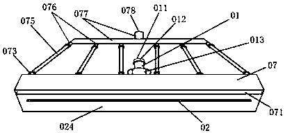
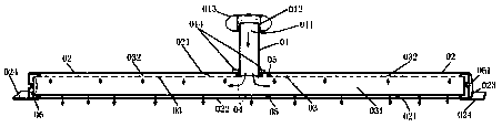
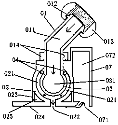
[0024] The device of the present invention is connected to the putty feeding device before working, or connected to a hard tube of a wiper rod and then connected to the feeding device. When working, the putty slurry enters the inner cavity slurry guide tube 03 from the feed inlet 011 The cavity 031 moves to its two ends, and then flows into the space gap of the outer cavity 021 through the inner and outer cavity channel holes 032 or the inner and outer cavity channel gaps, and is divided into two corresponding directions through the two-way extrusion of the narrow space of the outer cavity 021. After being distributed, the two are combined into one, and the thickness is uniformly extruded from the discharge gap 022 to the exit of the discharge gap 022, and then the putty slurry is wiped along the ceiling or wall through the long and straight scraper 024 The material is spread more evenly and evenly and scraped to the job; when constructing on the ceiling surface or the wall high...


PUM


Abstract

The invention discloses a ceiling face and wall face putty scraping device with automatic supplying and residual slurry automatic recovery functions. The ceiling face and wall face putty scraping device is constituted by a feeding pipe connector, a movable nut, locking nuts, an outer cavity slurry distributing pipe, supporting plate ribs, a scraping plate, an inner cavity slurry guiding pipe, sealing rubber rings, a fixing ring, a plugging head, a recovery pipe connector, a steel wire hose, a branch pipe and a hard pipe. The ceiling face and wall face putty scraping device mainly can be used for ceiling face putty scraping decoration construction, and can also be used for inner and outer wall face construction, the scraping face is wide, the speed is high, residual slurry generated duringscraping can be automatically recovered, flatness and straightness of the construction work surface process can be achieved, the ground is not polluted, the grinding time is reduced, the area of 120-250 square meters or above of the ceiling face can be scraped per hour, and construction through the ceiling face and wall face putty scraping device can be equivalent to construction through manpowerof 4-6 or more workers; and the ceiling face and wall face putty scraping device can overcome the defects and fill the blank of an existing putty scraping decorative technology and tool, manpower is saved, and the efficiency and quality are improved.

Description

Technical field [0001] The invention relates to a putty scraping tool in the field of building surface putty decoration machinery construction, in particular to a putty scraper for automatically feeding and automatically recovering residual slurry on a ceiling surface wall surface. Background technique [0002] In the existing indoor ceiling surface putty scraping construction process, traditional techniques are basically used. Workers use scaffolding to increase the height, put the slurry on the shelf in advance, use an elastic scraper, a gray knife, bend over, and reach out with a gray knife to remove the slurry. Take the material from the barrel, and then use the elastic scraper to scrape the ceiling surface back and forth. Due to the upward operation, the putty is not easy to stick, and it is easy to fall off and contaminate the ground. Workers exert a lot of physical effort. Standing on the scaffolding still poses a certain safety hazard. It takes a certain amount of time to...

Claims


Application Information

Patent Timeline
Patent Type & Authority Applications(China)
IPC IPC(8): E04F21/08
CPCE04F21/08
Inventor 应鸽龙
Owner 应鸽龙
Why Eureka
Try Eureka