A nuclear power plant pressure pipeline acoustic emission detector and method

A pressure pipeline and acoustic emission technology, applied in the pipeline system, gas/liquid distribution and storage, mechanical equipment, etc., can solve the problems of large measurement error and large deviation, reduce the response difference, increase the distance, and avoid the application of preset The effect of tension

Active Publication Date: 2020-11-24
NUCLEAR POWER INSTITUTE OF CHINA
View PDF17 Cites 0 Cited by
  • Summary
  • Abstract
  • Description
  • Claims
  • Application Information

AI Technical Summary

Problems solved by technology

[0007] The purpose of the present invention is to provide an acoustic emission detector for nuclear power plant pressure pipelines, which solves the problems of large corresponding deviations and large measurement errors caused by existing acoustic emission detection methods

Method used


Image

  • A nuclear power plant pressure pipeline acoustic emission detector and method

Examples


Embodiment 1

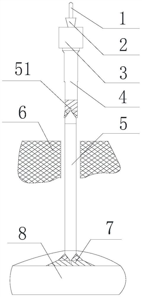
[0042] Such as figure 1 As shown, a nuclear power plant pressure pipeline acoustic emission detector includes a launch sensor 3, a signal cable 1 is arranged on the top of the launch sensor 3, and a first waveguide rod 4 is arranged on the bottom of the launch sensor 3 , the first waveguide rod 4 and the launch sensor 3 are integrated structures, and also include a second waveguide rod 5, one end of the second waveguide rod 5 is connected to the end of the first waveguide rod 4, and the other end is connected to the adapter seat 7 connection, the adapter seat 7 is installed on the main pipeline 8 or the wave pipe, the length of the second waveguide rod 5 is greater than the thickness of the insulation layer 6, and the connection method is welding, bonding or screw connection Compared with bonding and threaded connections, welding is more conducive to the propagation of acoustic emission signals. In order to improve the propagation characteristics of acoustic emission signals, ...

Embodiment 2

[0044] Such as figure 1 As shown, this embodiment is based on Embodiment 1. The two ends of the second waveguide rod 5 are tapered structures, and the ends of the tapered structure are small-sized ends, which are connected with the first waveguide rod 4 on the outside of the tapered structure. A welding zone is formed between the outside of the tapered structure and the adapter seat 7; the end of the tapered structure is provided with a positioning pin 51, and the end of the first waveguide rod 4 and the top of the adapter seat 7 are both provided There is a positioning hole matched with the positioning pin 51; the positioning pin 51 is a cylinder, and the positioning hole is a circular hole; the connection between the transmitting sensor 3 and the signal cable 1 is provided with a sealing structure 2, and the sealing The structure 2 is in contact with the top of the transmitting sensor 3, and the sealing structure 2 is provided with a through hole for passing the signal cable...

Embodiment 3

[0048] Such as figure 1As shown, this embodiment is based on Embodiment 1 or Embodiment 2. The adapter seat 7 is a trapezoidal structure with a large lower end and a small upper end; The material is consistent with or close to the main pipe 8 or the wave pipe.

[0049] Based on the detection method of the detector described in any one of embodiment 1 to embodiment 3, the described comprises the following steps:

[0050] 1), install the adapter seat 7 on the main pipe 8 or the wave pipe;

[0051] 2), connecting one end of the second waveguide rod 5 to the adapter seat 7;

[0052] 3), and then lay the insulation layer 6 on the main pipeline 8 or the wave pipe, so that the second waveguide rod 5 protrudes from the insulation layer 6;

[0053] 4) Connect the other end of the second waveguide 5 to the end of the first waveguide 4 . .


PUM


Abstract

The invention discloses an acoustic emission detector and method for a nuclear power plant pressure pipeline. The detector includes a transmitting sensor, a signal cable is arranged on the top of the transmitting sensor, and a first waveguide rod is arranged on the bottom of the transmitting sensor. The first waveguide rod and the transmitting sensor are of an integrated structure, and also include a second waveguide rod, one end of the second waveguide rod is connected to the end of the first waveguide rod, and the other end is connected to the adapter seat, and the adapter seat Installed on the main pipeline or wave pipe, the length of the second waveguide rod is greater than the thickness of the insulation layer. The invention solves the problems of large corresponding deviation and large measurement error caused by the existing acoustic emission detection method.

Description

technical field [0001] The invention relates to the technical field of high-pressure medium leakage detection, in particular to an acoustic emission detector and method for a nuclear power plant pressure pipeline. Background technique [0002] Acoustic emission technology is a dynamic nondestructive testing method developed rapidly after the 1950s. The signal comes from the defect itself, and the elastic wave released by the acoustic emission source carries a large amount of information about structural or material defects when propagating in the structure. [0003] The main pipe and wave pipe of nuclear power plant are important components of the primary cooling system of the reactor. The pipe contains a large amount of high-temperature and high-pressure coolant, so it is of great significance to monitor its defect and leakage. [0004] When the coolant escapes from cracks or corrosion holes in the pressure-bearing boundary of the pipeline, stress waves will be excited in t...

Claims


Application Information

Patent Timeline
Patent Type & Authority Patents(China)
IPC IPC(8): F17D5/06
CPCF17D5/06
Inventor 刘才学曾杰杨泰波何攀李朋洲彭翠云
Owner NUCLEAR POWER INSTITUTE OF CHINA
Why Eureka
Try Eureka