High-pressure gas conveying pipe leakage monitoring system and method

A technology for conveying pipelines and high-pressure gas, which is applied in pipeline systems, gas/liquid distribution and storage, mechanical equipment, etc., and can solve problems such as leak alarm positioning of high-pressure gas pipelines

Pending Publication Date: 2018-11-13
北京科力达宏业科贸有限责任公司
View PDF0 Cites 6 Cited by
  • Summary
  • Abstract
  • Description
  • Claims
  • Application Information

AI Technical Summary

Problems solved by technology

[0007] The purpose of the embodiment of the present invention is to provide a high-pressure gas delivery pipeline leakage monitoring system and method to solve the problem of leak alarm location of high-pressure gas delivery pipeline

Method used


Image

  • High-pressure gas conveying pipe leakage monitoring system and method

Examples


Embodiment 1

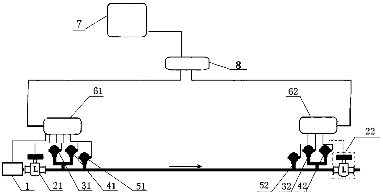
[0027] In this example combined figure 1 The leak monitoring system of high-pressure gas transmission pipeline is described. Such as figure 1 As shown, it includes: a first data acquisition and processing device 61 arranged in the first section of the high-pressure gas delivery pipeline, a first flow sensor 21, a first vibration signal sensor 31, a first pressure sensor 41, a first temperature sensor 51, and The second data acquisition and processing device 62, the second vibration signal sensor 32, the second pressure sensor 42, and the second temperature sensor 52 are arranged in the second section of the high-pressure gas delivery pipeline; the first section is located upstream of the second section.

[0028] The first flow sensor 21 is connected to the first data acquisition and processing device 61 through a shielded signal cable. The first flow sensor 21 is a high-precision flow signal sensor, and the collected flow signal can be sent to the first data collection and p...

Embodiment 2

[0051] An embodiment of the present invention provides a leakage monitoring method of a high-pressure gas transmission pipeline, which is applied to the high-pressure gas transmission pipeline leakage monitoring system described in the first aspect; the high-pressure gas transmission pipeline leakage monitoring method includes: collecting the flow rate of the first section of the high-pressure gas transmission pipeline Signal, vibration signal, pressure signal, temperature signal; collect the vibration signal, pressure signal, temperature signal of the second section of the high-pressure gas pipeline; the first section is located upstream of the second section; the flow signal of the first section , vibration signal, pressure signal, and temperature signal are sent to the first data acquisition and processing device 61, and the flow signal, vibration signal, pressure signal, and temperature signal of the first section are processed by the first data acquisition and processing de...


PUM


Abstract

The invention discloses a high-pressure gas conveying pipe leakage monitoring system and method. The high-pressure gas conveying pipe leakage monitoring system comprises a first data acquiring and processing device, a first flow sensor, a first vibration signal sensor, a first pressure sensor and a first temperature sensor arranged on a first section of a high-pressure gas conveying pipe, and a second data acquiring and processing device, a second vibration signal sensor, a second pressure sensor and a second temperature sensor arranged on a second section of the high-pressure gas conveying pipe; the first section is positioned at the upstream of the second section; the first flow sensor, the first vibration signal sensor, the first pressure sensor and the first temperature sensor are connected with the first data acquiring and processing device; and the first data acquiring and processing device is used for processing data acquired by the first flow sensor, the first vibration signalsensor, the first pressure sensor and the first temperature sensor to obtain first data to be analyzed.

Description

technical field [0001] The invention relates to the technical field of high-pressure gas delivery, in particular to a system and method for monitoring leakage of a high-pressure gas delivery pipeline. Background technique [0002] In the process of oil extraction, in order to increase production, technical means will be used to carry out oil displacement operations in underground oil layers, in which high-pressure pipelines are used to continuously inject CO into the oil layers. 2 It is a technology that is gradually becoming mature. [0003] Normally, CO 2 It is driven into the delivery pipeline by a high-pressure (10-20Mpa) pump and transported to the injection point. The delivery pipeline will be continuously under high-pressure operation (for example, 19Mpa operation), and the CO in the pipeline will 2 Generally, it is in a liquid state. Once such a high-pressure operation pipeline leaks and cannot be found in time, it will seriously affect the recovery rate of crude o...

Claims


Application Information

Patent Timeline
Patent Type & Authority Applications(China)
IPC IPC(8): F17D5/06F17D5/00
CPCF17D5/06F17D5/005
Inventor 任振山盛建姜存宝
Owner 北京科力达宏业科贸有限责任公司
Why Eureka
Try Eureka