
Micro heat pipe heating radiator and manufacturing method thereof

A technology of radiators and micro heat pipes, which is applied in the field of building heating and heating, can solve the problems of low low-temperature heat radiation capability, slow temperature rise of oil bath, and large water consumption of the system, and achieve high thermal conductivity, fast heat transfer speed, The effect of increasing the heat transfer area

Pending Publication Date: 2018-11-13
长沙馨麓能源科技有限公司
View PDF5 Cites 2 Cited by
  • Summary
  • Abstract
  • Description
  • Claims
  • Application Information

AI Technical Summary

Problems solved by technology

[0002] At present, the product update in my country's radiator market is slow, and there are disadvantages such as low heat dissipation efficiency, large system water consumption, poor pressure bearing capacity, leakage risk, and poor frost resistance.
As far as water heating is concerned, it has the characteristics of slow heat start, poor convection performance, and low low temperature heat radiation ability
As far as electric heating is concerned, different forms of electric heaters have certain performance defects, such as the characteristics of slow temperature rise of oil heaters and slow room temperature rise; convection heaters have the characteristics of high power consumption and low efficiency

Method used


Image

  • Micro heat pipe heating radiator and manufacturing method thereof
  • Micro heat pipe heating radiator and manufacturing method thereof
  • Micro heat pipe heating radiator and manufacturing method thereof

Examples


Embodiment 1

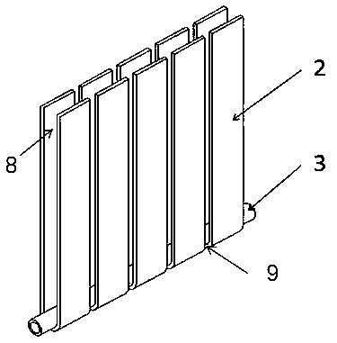
[0035] Embodiment 1: as figure 1 As shown, the superconducting water heating radiator is composed of a plate superconducting heat pipe 2 and a heat source pipe 3. The plate superconducting heat pipe 2 is bent into a U shape and arranged side by side with a certain gap between them. The internal interlayer forms a convection channel 8 The two sides of the lower end of the plate superconducting heat pipe are cold air inlets 9, and the outside of the plate superconducting heat pipe radiates heat from the air, and the structure of the heat sink is extremely simple.

Embodiment 2

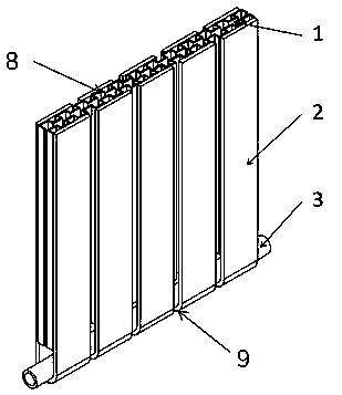
[0036] Embodiment 2: as figure 2 As shown, on the basis of the first embodiment, the superconducting water heating radiator adds fins 1 inside the plate superconducting heat pipe 2, and forms between the fins 1 and between the fins 1 and the plate superconducting heat pipe 2 The convection channel 8, the outside of the plate superconducting heat pipe 2 directly radiates heat with the air, and the lower end of the radiator is provided with a cold air inlet 9, which is beneficial to convection heat dissipation.

Embodiment 3

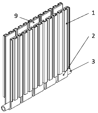
[0037] Embodiment 3: as image 3 As shown, on the basis of the first embodiment, the superconducting water heating radiator adds fins 1 on the outside of the plate superconducting heat pipe 2, and the inner side of the plate superconducting heat pipe 2 forms a convection channel 8, and the plate superconducting heat pipe 2 The outer fins 1 directly radiate and dissipate heat with the air, and the lower end of the radiator is provided with a cold air inlet 9, which is beneficial to convective heat dissipation.


PUM


Abstract

The invention relates to a micro heat pipe heating radiator and a manufacturing method thereof. The micro heat pipe heating radiator comprises plate type super heat conducting pipes, fins and a heat source pipe, wherein the heat source of the heat source pipe can be an electric heater or hot water. The lower segments of the plate type super heat conducting pipes are attached to the heat source pipe, and the upper segments of the plate type super heat conducting pipes are attached to the fins. The plate type super heat conducting pipes are of flat or U-shaped structures. Air inlets are formed in the lower portion of the micro heat pipe heating radiator, air outlets are formed in the upper portion of the micro heat pipe heating radiator, heat of the heat source pipe is fast transmitted intothe air through the plate type super heat conducting pipes, and indoor heating is achieved. The heating radiator has convection heat dissipation as well as having radiation heat dissipation. The microheat pipe heating radiator has the advantages of being quick in temperature rising, low in operating temperature, large in heat dissipation amount, high in heat exchanging efficiency, remarkable in energy saving, large in pressure bearing capability, high in corrosion resistance, not prone to heating a wall, long in service life, good in anti-frost property, high in corrosion resistance, safe inoperation and the like. The micro heat pipe heating radiator adopts a modular splicing manufacturing method, and the micro heat pipe heating radiator is easy and convenient to manufacture, high in metal heat strength, ultralight and ultrathin, and is novel heating equipment with wide market application prospects.

Description

technical field [0001] The invention relates to the technical field of building heating, in particular to a micro heat pipe radiator and a manufacturing method thereof. Background technique [0002] At present, the product update in my country's radiator market is slow, and there are disadvantages such as low heat dissipation efficiency, large system water consumption, poor pressure bearing capacity, leakage risk, and poor frost resistance. As far as water heating is concerned, it has the characteristics of slow heat start, poor convection performance, and low low temperature heat radiation ability. As far as electric heating is concerned, different forms of electric heaters have certain performance defects, such as the characteristics of slow temperature rise of oil heaters and slow room temperature rise; convection heaters have the characteristics of high power consumption and low efficiency . Contents of the invention [0003] The object of the present invention is to...

Claims


Application Information

Patent Timeline
Patent Type & Authority Applications(China)
IPC IPC(8): F28D15/02F24D19/00
CPCF24D19/00F28D15/02
Inventor 江乐新费凡
Owner 长沙馨麓能源科技有限公司
Learn More