
A heat exchanger for chemical production

A technology for heat exchangers and chemical production, which is applied in the field of heat exchangers for chemical production, which can solve problems such as inconvenient installation and achieve the effect of reducing volume and improving heat exchange efficiency

Active Publication Date: 2019-12-03
GBXF SILICONES CO LTD
View PDF5 Cites 0 Cited by
  • Summary
  • Abstract
  • Description
  • Claims
  • Application Information

AI Technical Summary

Problems solved by technology

In the prior art, in order to make the liquid heated evenly, it is necessary to install a series of external devices to stir the liquid, and even the installation is inconvenient

Method used


Image

  • A heat exchanger for chemical production
  • A heat exchanger for chemical production
  • A heat exchanger for chemical production

Examples


Embodiment approach

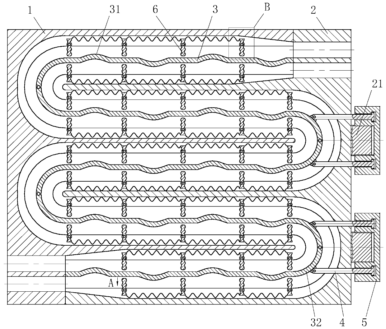
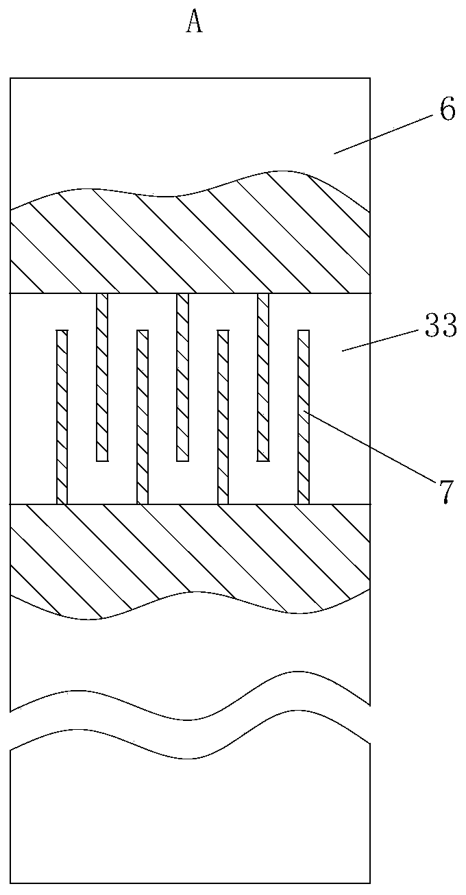
[0035] As the first embodiment of the drainage groove 33 in the present invention, the two sides of the drainage groove 33 of the swing plate 6 are alternately provided with baffles 7; one end of the baffle 7 is fixedly connected to the side wall of the drainage groove 33; When working, the flowing liquid pushes the oscillating plate 6 to swing after overcoming the elastic force of the torsion spring, and the flowing liquid bypasses the baffle plate 7 in the drainage groove 33 on the oscillating plate 6 and then discharges, and the liquid bends in the drainage groove 33 on the oscillating plate 6 Heat exchange is performed through the heat exchange partition plate 3 during the flowing process, and the liquid constantly changing the direction of movement further improves the heat exchange efficiency.

[0036] As the second embodiment of the drainage groove 33 in the present invention, sliding grooves 331 are arranged on both sides of the drainage groove 33 of the swing plate 6, ...


PUM


Abstract

The invention belongs to the technical field of heat exchangers, and particularly relates to a heat exchanger for chemical industry production. The heat exchanger comprises a left shell, a right shelland a heat exchange separating plate, and the right shell and the left shell are installed together in a staggered manner; and the heat exchange separating plate is arranged in a cavity composed of arectangular groove of the left shell and a rectangular groove of the right shell, the left end corner arc position of the heat exchange separating plate is hinged to the side wall of the rectangulargroove of the left shell through a rotating shaft, and the right end corner arc position of the heat exchange separating plate is hinged to the side wall of the rectangular groove of the right shell through a rotating shaft. The heat exchange separating plate is arranged in the cavity composed of the rectangular groove of the left shell and the rectangular groove of the right shell, two kinds of liquid on the two sides of the heat exchange separating plate are subjected to heat exchange through the heat exchange separating plate, an industrial cycle solution is cooled, the industrial cycle solution obtained after heat exchange and cooling water are discharged out from the interior of a through hole in the upper end of the right shell.

Description

technical field [0001] The invention belongs to the technical field of heat exchangers, in particular to a heat exchanger for chemical production. Background technique [0002] A heat exchanger, also known as a heat exchanger, is a device used to transfer heat from a hot fluid to a cold fluid to meet the specified process requirements. It is an industrial application of convective heat transfer and heat conduction. Heat exchangers are common equipment in chemical industry, petroleum, power, food and many other industrial sectors, and play an important role in production. In chemical production, heat exchangers can be used as heaters, coolers, condensers, evaporators and reboilers, etc., and are more widely used. [0003] There are many types of heat exchangers, but according to the principle and method of heat exchange between cold and hot fluids, they can basically be divided into three categories: partition type, hybrid type and heat storage type. Among the three types o...

Claims


Application Information

Patent Timeline
Patent Type & Authority Patents(China)
IPC IPC(8): F28D21/00
CPCF28D21/00
Inventor 李洁
Owner GBXF SILICONES CO LTD
Learn More