Disassembling method and disassembling line for anti-tank mine

A technology for landmines and tanks, which is applied to weapons accessories, ammunition, offensive equipment, etc., can solve the problems of slow dismantling speed, reliability, safety degradation, and high site conditions, so as to ensure the safety of dismantling, eliminate potential safety hazards, Removes the effect of contact with explosives

Inactive Publication Date: 2018-11-13
重庆航天工业有限公司
View PDF6 Cites 2 Cited by
  • Summary
  • Abstract
  • Description
  • Claims
  • Application Information

AI Technical Summary

Problems solved by technology

[0002] As an important part of engineering equipment, anti-tank landmines usually have a large number of reserves and a variety of varieties. After long-term storage, their reliability and safety decline, which poses a huge security threat to society. Therefore, it is necessary to properly destroy and dispose of waste landmines
[0003] The traditional destruction methods of obsolete landmines mainly include explosion method, combustion method, chemical decomposition method and manual disassembly method, etc. These methods have their own advantages and disadvantages, such as explosion method and combustion method. It is highly toxic, pollutes the environment, and resources cannot be recycled; chemical decomposition methods such as deep well burial, deep sea dumping, etc. have high requirements on site conditions and are likely to leave potential safety hazards; although manual disassembly methods can achieve resource recycling, but the labor cost is high, The dismantling speed is slow, and there is a threat to personal safety at the operation site. Therefore, a dismantling method and dismantling line that can automatically dismantle anti-tank mines are needed

Method used


Image

  • Disassembling method and disassembling line for anti-tank mine
  • Disassembling method and disassembling line for anti-tank mine
  • Disassembling method and disassembling line for anti-tank mine

Examples


Embodiment 1

[0043] Example 1, see Figure 1 to Figure 15 , a kind of anti-tank landmine dismantling method, comprises the following steps:

[0044] The first step, casing cutting: cut an annular groove on the outer periphery of the mine casing by means of rotary cutting, and the depth of the groove is smaller than the wall thickness of the casing;

[0045] The second step, shell extrusion: form a crack through the wall thickness of the shell at the root of the annular groove by extrusion, so that the mine shell is decomposed into two parts: the shell and the mine cover;

[0046] The third step is to separate the shell: take the groove as the dividing line, and separate the ground shell and the mine cover by pulling;

[0047] The fourth step is to pour the explosives: the explosives remaining in the casing and the mine cover after separation are shaken out by vibration.

[0048] In the casing cutting step of the first step, the section of the annular groove formed by cutting is V-shaped....

Embodiment 2

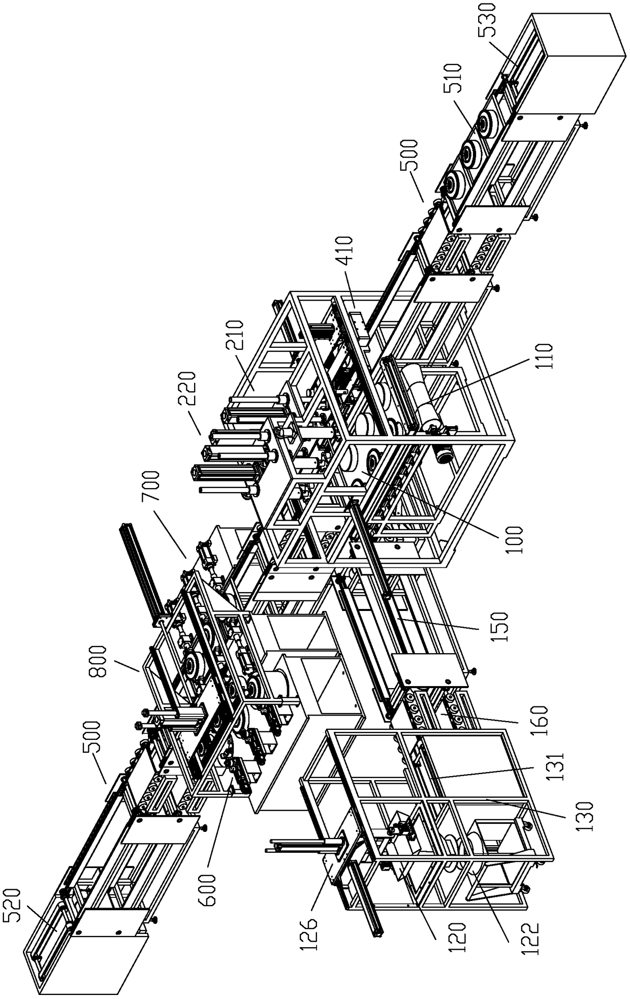
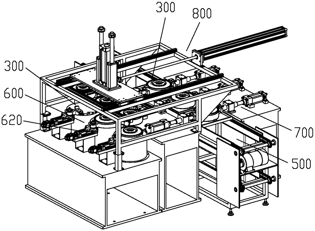
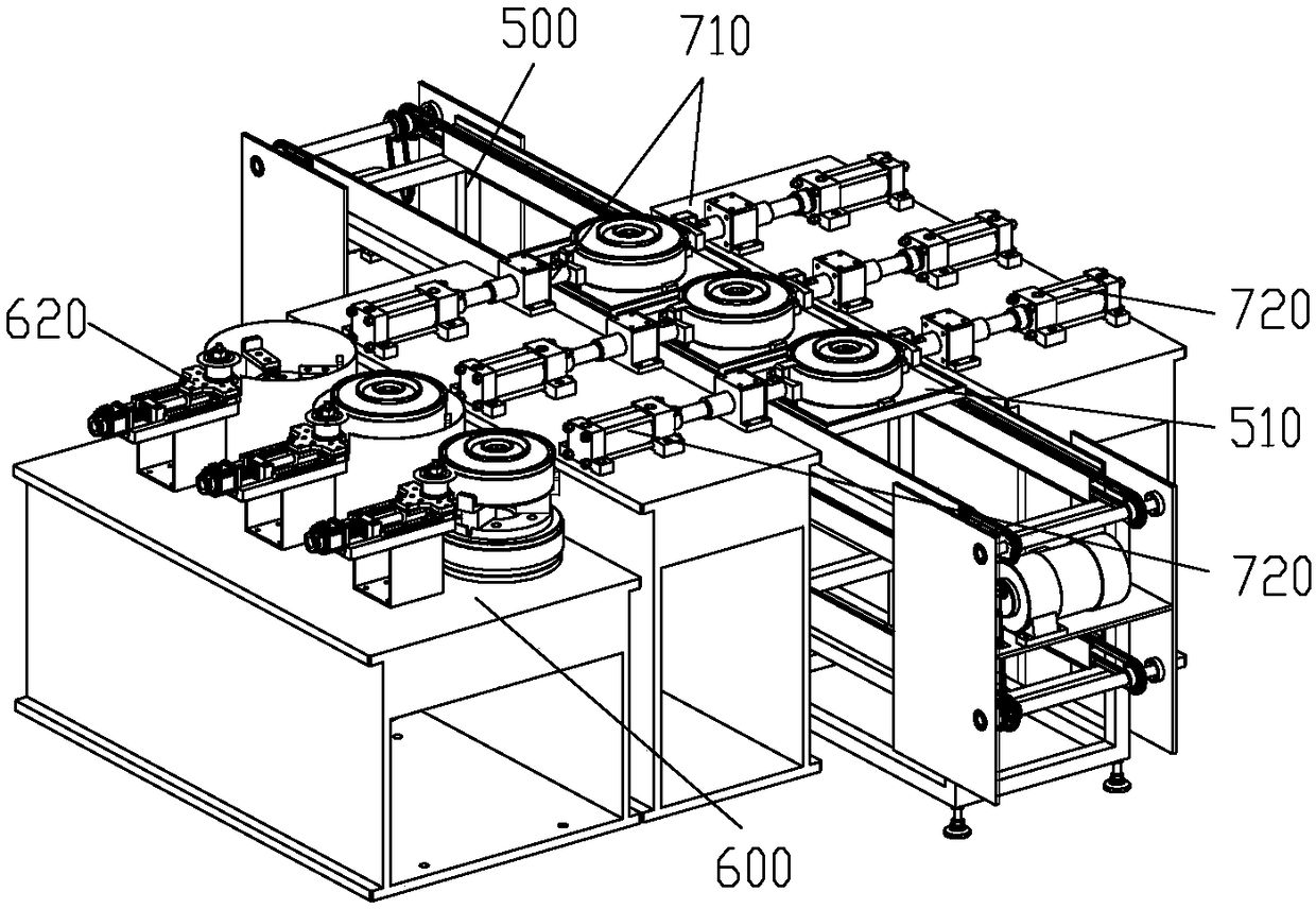
[0050] Example 2, see Figure 1 to Figure 15 , a dismantling line for anti-tank landmines, comprising a shell cutting unit 600, a shell disassembling unit 700, and a vibrating pouring unit connected in sequence by a material delivery unit; the shell cutting unit 600 is composed of a vertical rotary power head 610 and a horizontally moving The cutting tool holder 620 is composed of the shell cutting unit 600 for cutting annular grooves on the shell of the mine; the shell dismantling unit 700 includes at least two hydraulically driven extrusion heads 710 distributed around the circumference, and the shell dismantling unit 700 is used for hydraulically The way of extruding the annular groove forms a penetrating crack at the root of the groove, so that the shell of the mine is separated into the shell and the cover of the mine; The first vibration source 210 and the second vibration source 220 are composed of the first vibration source 210 and the second vibration source 220 of th...


PUM


Abstract

The invention discloses a disassembling method and a disassembling line for an anti-tank mine. The disassembling method comprises the following steps that an outer shell is cut, wherein an annular groove is cut in the periphery of the outer shell of the mine in a rotary cutting mode, wherein the depth of the groove is smaller than the wall thickness of the shell; the outer shell is extruded, wherein a crack penetrating through the wall thickness of the outer shell is formed at the root of the annular groove in an extruding mode to enable the outer shell of the mine to be broken into two parts,namely, a shell body and a mine cover; the outer shell is separated, wherein by taking the annular groove as a boundary, the mine shell body and the mine cover are separated through pulling and dragging; and explosive is dumped, wherein the explosive left in the shell body and the mine cover after separation is shaken out in a vibrating mode correspondingly. The disassembling line comprises an outer shell cutting unit, an outer shell breaking unit and an explosive vibrating dumping unit which are used for providing facility guarantee for the disassembling method correspondingly. The disassembling method and the disassembling line have the beneficial effects that automatic disassembling of the mine can be realized through the disassembling method, and the disassembling method is high in disassembling efficiency, good in safety, and low in disassembling cost; and the disassembling line is characterized in that corresponding functions are achieved through reasonable equipment configuration, and a compact disassembling line structure is formed through a reasonable layout mode.

Description

technical field [0001] The invention relates to a dangerous article dismantling and destruction technology, in particular to a dismantling method and a dismantling line of an anti-tank landmine. Background technique [0002] As an important part of engineering equipment, anti-tank landmines are usually stored in large quantities and in various varieties. After long-term storage, their reliability and safety decline, posing a huge security threat to society. Therefore, waste landmines must be properly destroyed and disposed of. [0003] The traditional destruction methods of obsolete landmines mainly include explosion method, combustion method, chemical decomposition method and manual disassembly method, etc. These methods have their own advantages and disadvantages, such as explosion method and combustion method. It is highly toxic, pollutes the environment, and resources cannot be recycled; chemical decomposition methods such as deep well burial, deep sea dumping, etc. have...

Claims


Application Information

Patent Timeline
Patent Type & Authority Applications(China)
IPC IPC(8): F42B33/06
Inventor 杜木伟黄贵何赵晓丽文宏平
Owner 重庆航天工业有限公司
Why Eureka
Try Eureka