Optical amplification module of folding optical path

A technology of optical amplification and modules, which is applied in optics, optical components, instruments, etc., can solve the problems of increasing system uncertainty and errors, many phase retarders, and decreased accuracy, so as to shorten the size and volume, expand the The effect of the angle of view and low adjustment difficulty

Pending Publication Date: 2018-11-13
CHENGDU IDEALSEE TECH
View PDF6 Cites 9 Cited by
  • Summary
  • Abstract
  • Description
  • Claims
  • Application Information

AI Technical Summary

Problems solved by technology

This kind of structure is relatively complicated, and there are many phase retarders, which reduces the accuracy of the

Method used


Image

  • Optical amplification module of folding optical path
  • Optical amplification module of folding optical path
  • Optical amplification module of folding optical path

Examples


Embodiment 1

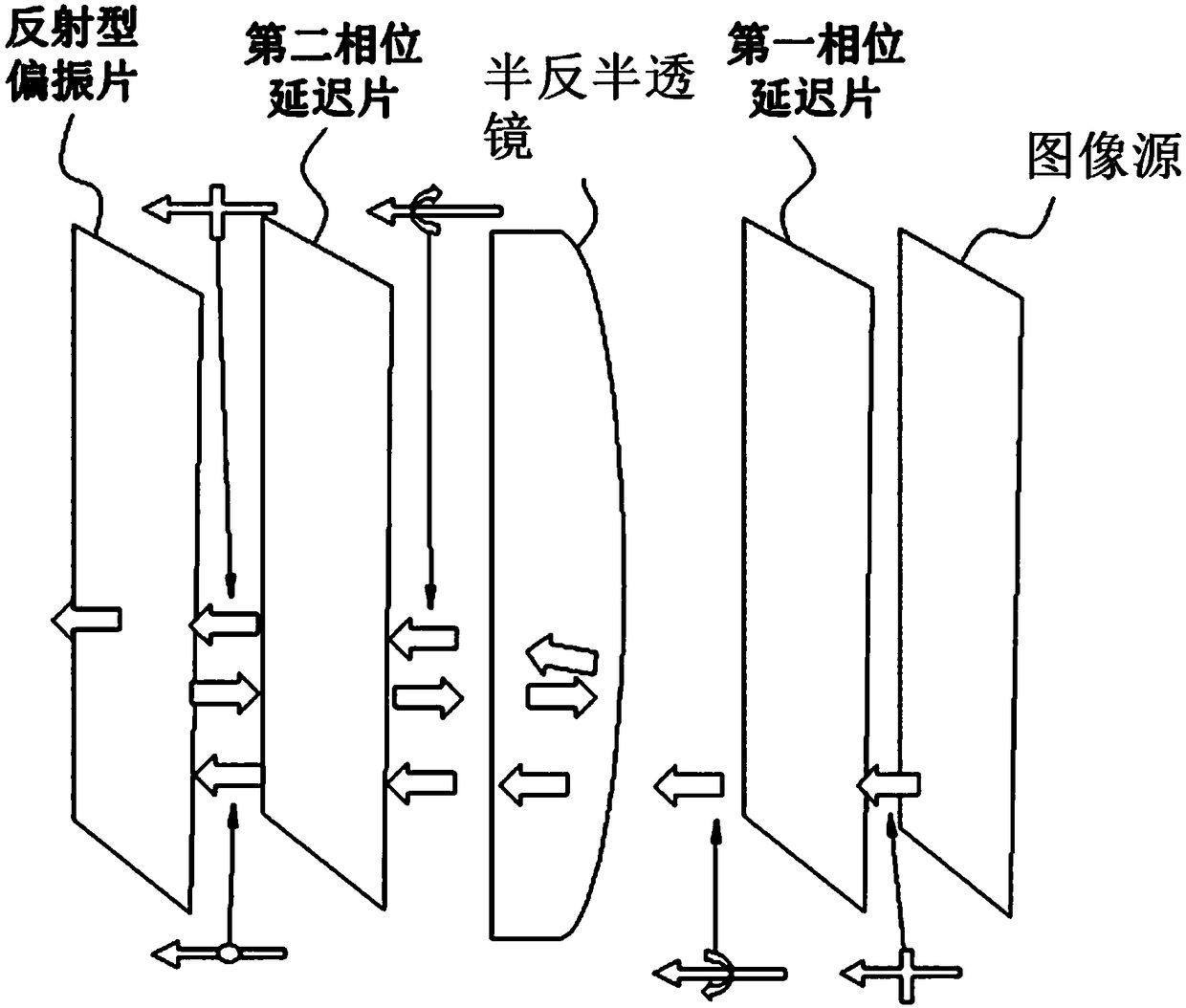
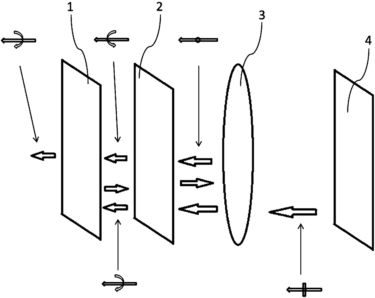
[0035] Such as figure 2 As shown, an optical amplification module with a folded optical path is arranged on the outgoing optical path of the image source 4, and includes an imaging lens 3, a phase retarder 2, and a circularly polarized transflective selector 1 sequentially arranged on a common optical path; the imaging The refractive power of the lens 3 is positive, and the optical surface close to the image source 4 is a coated optical surface, and the imaging lens 3 transmits and amplifies part or all of the optical image with the first linear polarization direction emitted by the image source 4; the phase retarder 2 Arranged on the optical path of the optical image having the first linear polarization direction after passing through the imaging lens 3, the phase retarder 2 converts the polarization direction of the optical image from the first linear polarization direction to the first circular polarization direction and then transmits it to the circularly polarized light ...

Embodiment 2

[0048] Based on the structure in Example 1, in this example, as Figure 4 As shown, the metasurface layer is composed of multi-layer concentric annular structures; each layer of annular structure is composed of multiple microstructures to form an annular shape, and any two microstructures can be translated and overlapped , each microstructure is a planar chiral body, and the straight-line distance between the two endpoints of the microstructure is less than 380nm. The metasurface layer of this structure can realize the transflective selection of circularly polarized light. The transflective properties of the metasurface structure composed of font-shaped planar chirals reflect left-handed circularly polarized light and transmit right-handed circularly polarized light (see reference [2] for the principle);

[0049] In addition, the microstructures in adjacent annular structures have angle differences between each other, refer to Figure 4 , the angle difference refers to the an...

Embodiment 3

[0051] In the case based on Embodiment 1 and Embodiment 2, the transflective properties of the circularly polarized transflective selector 1 can be made to reflect right-handed circularly polarized light and transmit left-handed circularly polarized light, and only need to adjust the phase retarder accordingly 2. The angle of the fast axis or the first linear polarization direction only needs to make the first circular polarization direction be left-handed circularly polarized light. This kind of adaptive adjustment method is relatively simple and will not be repeated here. The transflective properties of the circularly polarizing transflective selector 1 are determined after fabrication.


PUM


Abstract

The invention relates to the field of optical amplification, and provides an optical amplification module of a folding optical path. The optical amplification module of a folding optical path comprises an imaging lens, a phase retarder and a circularly polarized transflective selector, wherein the imaging lens, the phase retarder and the circularly polarized transflective selector arranged in theoptical path successively; linearly polarized optical images pass the three devices successively; when the phase retarder performs polarization conversion on the passed optical images and the circularly polarized transflective selector performs transflective selection on the circularly polarized light, the optical images pass the imaging lens for two times so as to be amplified; and the actual system length of the optical amplification module is less than the equivalent system length, and the system can realize optical amplification in a short distance condition by using only the three devices. Therefore, the optical amplification module of a folding optical path has the advantages of being low in regulating difficulty, being low in complexity of the optical path, and having no excessive nondeterminacy.

Description

technical field [0001] The invention relates to the field of optical amplification, in particular to an optical amplification module with folded optical paths. Background technique [0002] Existing short-distance optical magnification modules with aberration correction functions such as figure 1 As shown, it consists of an image source, a first phase retarder, a second phase retarder, a partially transmissive and partially reflective mirror with a curved surface, and a reflective polarizer. Assuming that the reflective polarizer in the figure reflects horizontally polarized light and transmits vertically linearly polarized light, it is assumed that the image source emits an optical image that is linearly polarized in the vertical direction and becomes the first circularly polarized optical image through the first phase retarder. The optical image of the first circular polarization is amplified for the first time through the partial transmission and partial reflection mirro...

Claims


Application Information

Patent Timeline
IPC IPC(8): G02B27/28G02B27/00
CPCG02B27/0081G02B27/28
Inventor 宋海涛高一峰陈超
Owner CHENGDU IDEALSEE TECH
Why Eureka
Try Eureka