Switch reluctance motor

A technology of switched reluctance motors and rotors, which is applied in the direction of electrical components, electromechanical devices, magnetic circuit static parts, etc. It can solve the problem of small starting torque, reduce torque ripple, reduce rotor saturation, and output average rotation speed The effect of moment enhancement

Inactive Publication Date: 2018-11-13
淮北思尔德电机有限责任公司
View PDF6 Cites 2 Cited by
  • Summary
  • Abstract
  • Description
  • Claims
  • Application Information

AI Technical Summary

Problems solved by technology

[0004] In order to solve the deficiencies in the prior art, the object of the present invention is to provide a switched reluctance motor, which solves the problem of small starting torque while reducing noise by improving the performance of the motor

Method used


Image

  • Switch reluctance motor
  • Switch reluctance motor
  • Switch reluctance motor

Examples


Embodiment 1

[0019] A switched reluctance motor, through changing the curvature of the top of the rotor pole teeth, a variable air gap is formed between the rotor and the stator, thereby changing the inductance performance of the motor, increasing the starting torque, increasing the output torque, and reducing torque ripple.

Embodiment 2

[0021] As a specific structure of Embodiment 1, the stator teeth poles are pole shoe pole teeth, and the rotor tooth poles are flat arc pole teeth with variable air gap.

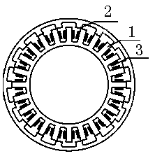
[0022] Such as figure 1 , 2 , as shown in 3, where figure 1 It is a hub-type external rotor motor, the inner ring is the stator 1, and there are 24 tooth poles on the stator 1, and the outer ring is the rotor 2, and there are 18 tooth poles on the rotor 2. Each stator 1 pole tooth has a winding 3, a total of twenty-four, and every three individual windings 3 are connected in series to form a phase. The windings are divided into ABCD four-phases, and each phase has six windings.

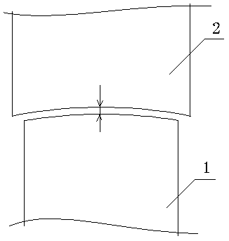
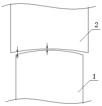
[0023] figure 2 The middle is the existing equidistant structure, the air gap is generally fixed at 3mm, and image 3 The flat arc structure is adopted in the center, and the air gap is a comparable gap, with the longest and shortest points.

Embodiment 3

[0025] As a specific structure of Embodiment 2, the single-side air gap between the rotor and the stator is between 1.7 mm and 3 mm, and as the rotor rotates, the length of the air gap between the rotor pole teeth and the stator pole teeth changes continuously.

[0026] The shortest part of the air gap is 0.18mm, and the longest is 0.37mm. When the rotor rotates clockwise, the air gap is larger when the air gap is 0.37mm, and the minimum value of the inductance is smaller than before. The minimum point of the air gap is 0.18mm at this time. Since the total air gap area is the same, the maximum inductance value is almost the same as that of the prior art. Figure 4 The inductance characteristic diagram in the figure is the same as the analysis. Among the figures, a is the inductance curve of the prior art, and b is the inductance curve of the present invention. It can be seen that the inductance curve of the present invention has a longer minimum inductance zone and the same max...


PUM


Abstract

The invention discloses a switch reluctance motor. By changing of top end radian of each rotor pole tooth, a variable air gap is formed between a rotor and a stator, so that inductance of the motor ischanged, a starting torque is increased, an output torque is increased, and torque ripple is reduced. By adoption of a variable air gap structure, the stator on the inner periphery comprises twenty-four stator tooth poles, the rotor on the outer periphery comprises eighteen rotor pole teeth, twenty-four winding coils include four phases A, B, C and D, every six windings in each phase are in series connection, the maximum torque of each single phase is high, each position of the maximum torque is appropriate, and torque ripple reduction and output torque increase are realized after superposition. Under a starting condition, in single-phase excitation, the peak torque is increased by 40% due to changing of an inductance performance curve; under a rated speed condition, due to air gap variability, the rotor saturation degree is decreased, the average output torque is increased by 1.4%, and the torque ripple is reduced by 38%.

Description

technical field [0001] The invention relates to a motor, in particular to a switched reluctance motor. Background technique [0002] The switched reluctance motor (SRM) used in the switched reluctance motor speed control system is the part of the SRD to realize the electromechanical energy conversion, and it is also the main symbol that the SRD is different from other motor drive systems. SRM series double salient pole variable reluctance motor, the salient poles of the stator and rotor are laminated by ordinary silicon steel sheets. The rotor has neither windings nor permanent magnets. There are concentrated windings on the stator poles. The two radially opposite windings are connected together, which is called "one phase". The SR motor can be designed into a variety of different phase structures, and the stator and rotor There are many different combinations of poles. [0003] The number of phases is large and the step angle is small, which is beneficial to reduce the to...

Claims


Application Information

Patent Timeline
Patent Type & Authority Applications(China)
IPC IPC(8): H02K1/14H02K1/22
CPCH02K1/14H02K1/22H02K2213/03
Inventor 徐志浩
Owner 淮北思尔德电机有限责任公司
Why Eureka
Try Eureka