Switch reluctance motor and vehicle power motor assembly

A technology for switched reluctance motors and stator poles, applied to synchronous motors with stationary armatures and rotating magnets, electrical components, electromechanical devices, etc. The problems such as low height and unstable operation of switched reluctance motor can achieve the effect of reducing radial vibration, improving efficiency and reducing torque ripple

Inactive Publication Date: 2018-11-13
石镇德
View PDF7 Cites 2 Cited by
  • Summary
  • Abstract
  • Description
  • Claims
  • Application Information

AI Technical Summary

Problems solved by technology

However, the traditional switched reluctance motor still has the following disadvantages: 1. The radial vibration generated by the traditional switched reluctance motor during operation and the salient pole structure of the stator and rotor are the main reasons for the noise of the switched reluctance motor; 2. 1. The torque ripple generated by the traditional switched reluctance motor during operation is the main reason for the unstable operation and low efficiency of the switched reluctance motor; 3. The power density of the traditional switched reluctance motor is not high; 4. The traditional The control system of the four-phase or five-phase or more-phase switched reluctance motor is complex; 5. The traditional switched reluctance motor has not been effectively used in vehicles

Method used


Image

  • Switch reluctance motor and vehicle power motor assembly
  • Switch reluctance motor and vehicle power motor assembly
  • Switch reluctance motor and vehicle power motor assembly

Examples


Embodiment Construction

[0024] In order to enable those skilled in the art to better understand the present invention, specific embodiments of the present invention will be described in detail below in conjunction with the accompanying drawings.

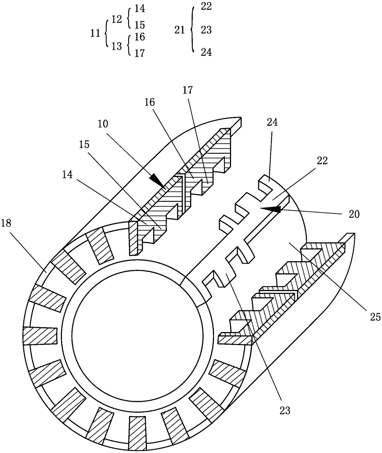
[0025] figure 1 is a schematic structural diagram of a switched reluctance motor according to an embodiment of the present invention.

[0026] refer to figure 1 , shows the structure of a switched reluctance motor according to an embodiment of the present invention. In this embodiment, the switched reluctance motor may have an inner rotor outer stator structure or an inner stator outer rotor structure. For ease of description, a switched reluctance motor with an inner rotor and outer stator structure is taken as an example below.

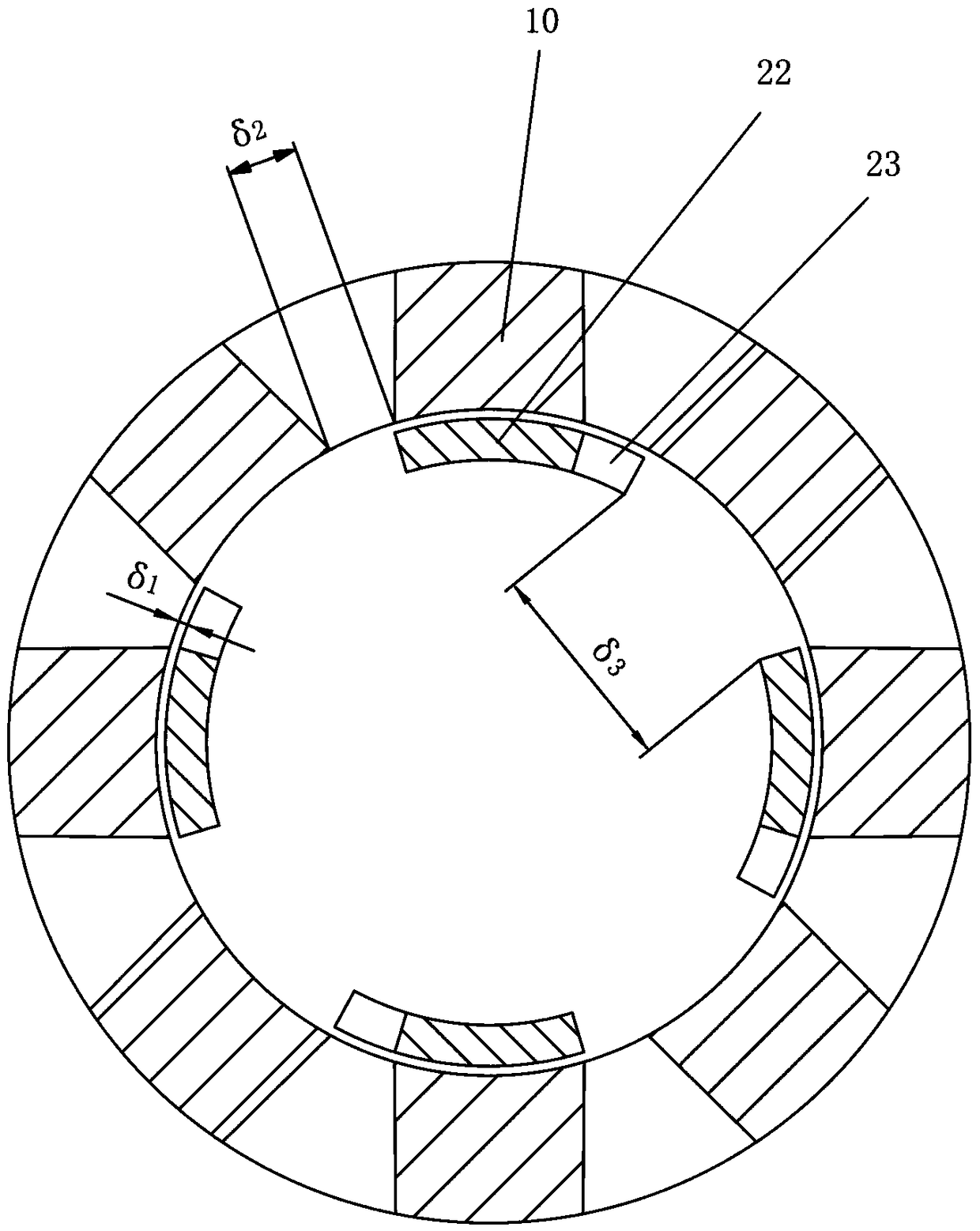
[0027] The switched reluctance motor may include a coaxially arranged stator 10 and a rotor 20 , the stator 10 may include a plurality of stator poles 11 uniformly distributed in the circumferential direction, and a coil (not ...


PUM


Abstract

The invention provides a switch reluctance motor and a vehicle power motor assembly. The switch reluctance motor comprises a stator and a rotor, the stator comprises multiple stator magnetic poles uniformly distributed peripherally, each stator magnetic pole comprises a first stator magnetic pole unit and a second stator magnetic pole unit, each first stator magnetic pole unit comprises a first stator magnetic pole root portion extending axially and multiple first stator magnetic pole tooth portions radially extending from the first stator magnetic pole root portion to the rotor, and each second stator magnetic pole unit comprises a second stator magnetic pole root portion extending axially and multiple second stator magnetic pole tooth portions radially extending from the second stator magnetic pole root portion to the rotor; the rotor comprises multiple rotor magnetic poles uniformly distributed peripherally, each rotor magnetic pole comprises a rotor magnetic pole root portion, multiple first rotor magnetic pole tooth portions and multiple second rotor magnetic pole tooth portions, the first rotor magnetic pole tooth portions extend peripherally from one side of the corresponding rotor magnetic pole root portion, and the second rotor magnetic pole tooth portions peripherally extend from the other side of the corresponding rotor magnetic pole root portion.

Description

technical field [0001] The invention relates to the field of switched reluctance motors, in particular to a switched reluctance motor integrated with a hollow rotor structure and an automotive power motor assembly including the switched reluctance motor. Background technique [0002] At present, more and more people begin to pay attention to the application of switched reluctance motor. However, the traditional switched reluctance motor still has the following disadvantages: 1. The radial vibration generated by the traditional switched reluctance motor during operation and the salient pole structure of the stator and rotor are the main reasons for the noise of the switched reluctance motor; 2. 1. The torque ripple generated by the traditional switched reluctance motor during operation is the main reason for the unstable operation and low efficiency of the switched reluctance motor; 3. The power density of the traditional switched reluctance motor is not high; 4. The traditio...

Claims


Application Information

Patent Timeline
Patent Type & Authority Applications(China)
IPC IPC(8): H02K21/14H02K21/02H02K29/03
CPCH02K21/02H02K21/14H02K29/03
Inventor 石镇德
Owner 石镇德
Why Eureka
Try Eureka