
Narrow-pulse peak sampling hold circuit

A peak sampling and holding circuit technology, applied in the direction of pulse processing, pulse technology, electrical components, etc., can solve the problems of low peak voltage value, unable to maintain the peak value of small-amplitude narrow pulse signal, etc., and achieve the effect of small voltage peak loss

Pending Publication Date: 2018-11-13
NORTH ELECTRON RES INST ANHUI CO LTD
View PDF14 Cites 8 Cited by
  • Summary
  • Abstract
  • Description
  • Claims
  • Application Information

AI Technical Summary

Problems solved by technology

[0005] The technical problem to be solved by the present invention is to provide a monolithic integrated narrow pulse peak hold circuit based on a standard CMOS process, which solves the problem of the traditional peak hold circuit by presetting the static operating point of the comparator second gain stage through local negative feedback. The problem of being unable to maintain the peak value of a small-amplitude narrow pulse signal or keep the peak voltage value low

Method used


Image

  • Narrow-pulse peak sampling hold circuit
  • Narrow-pulse peak sampling hold circuit
  • Narrow-pulse peak sampling hold circuit

Examples


Embodiment Construction

[0023] The present invention will be further described below in conjunction with the accompanying drawings. The following examples are only used to illustrate the technical solution of the present invention more clearly, but not to limit the protection scope of the present invention.

[0024] 1. Principle

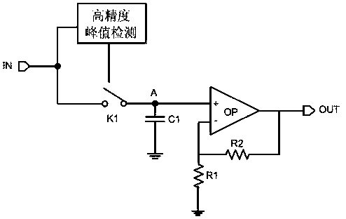
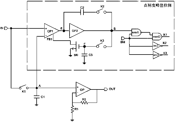
[0025] The principle of the invention is as figure 1 Shown: When the high-precision peak detection module detects the peak value of the narrow pulse IN, the control switch K1 is turned off, and the peak voltage is maintained at point A, which is the non-inverting input terminal of the operational amplifier OP; capacitor C1 is the on-chip holding capacitor, and the operational amplifier OP Point A of the non-inverting input terminal is grounded through capacitor C1. The inverting input terminal of the operational amplifier OP is grounded through the resistor R1, and the output terminal of the operational amplifier OP is fed back to the inverting input terminal of the opera...


PUM


Abstract

The invention discloses a narrow-pulse peak sampling hold circuit. The narrow-pulse peak sampling hold circuit is characterized in that a narrow pulse IN is detected by a high-precision peak detectionmodule and is input into a point A through a first switch K1 controlled by the high-precision peak detection module, the point A is grounded through a first capacitor, and meanwhile, the output voltage OUT is taken as final output sampling hold voltage after a signal of the point A passes through a total operational amplifier OP; after the high-precision peak detection module detects the peak voltage of the narrow pulse IN, the first switch K1 is controlled to be disconnected, so that the peak voltage is held at the point A. According to the narrow-pulse peak sampling hold circuit, a method of presetting a second gain stage static working point of a comparator through the local negative feedback is provided, so that a problem that a traditional peak hold circuit cannot hold a peak value of a small-amplitude narrow-pulse signal or hold a lower peak voltage value is solved, and the loss of the held voltage peak is smaller.

Description

technical field [0001] The invention relates to an analog integrated circuit technology, in particular to a monolithic integrated narrow pulse peak holding circuit. Background technique [0002] The high precision of laser guidance can greatly improve the throwing accuracy and hit rate of tactical weapons. In laser guidance, processing the echo signal received by the detector is a key technical link. The laser guidance signal processing circuit is used to pre-process the electrical signal output by the optical detection component, and complete the identification, amplification, retention and digital conversion of the detection signal. When the detected target is far away from the laser transmitter, the echo signal is weak, and the electrical signal output by the photodetector is also very weak, which is only a narrow pulse with a small amplitude in the order of ns, and it is difficult for high-speed AD to capture the narrow pulse. Therefore, it is necessary to design a pea...

Claims


Application Information

Patent Timeline
Patent Type & Authority Applications(China)
IPC IPC(8): H03K5/1532
CPCH03K5/1532
Inventor 白涛刘小淮陈远金
Owner NORTH ELECTRON RES INST ANHUI CO LTD
Learn More