Dynamic pressure plasma synthesis jet generator

A plasma and synthetic jet technology, applied in the direction of plasma, electrical components, etc., can solve the problem of jet energy limited thermoelectric conversion module power, etc., and achieve the effect of avoiding efficiency loss

Inactive Publication Date: 2018-11-13
XIAMEN UNIV
View PDF9 Cites 6 Cited by
  • Summary
  • Abstract
  • Description
  • Claims
  • Application Information

AI Technical Summary

Problems solved by technology

This synthetic jet device can only be applied under hypersonic conditions, and the jet energy is limited by the power of the thermoelectric conversion module.

Method used


Image

  • Dynamic pressure plasma synthesis jet generator
  • Dynamic pressure plasma synthesis jet generator

Examples


Embodiment Construction

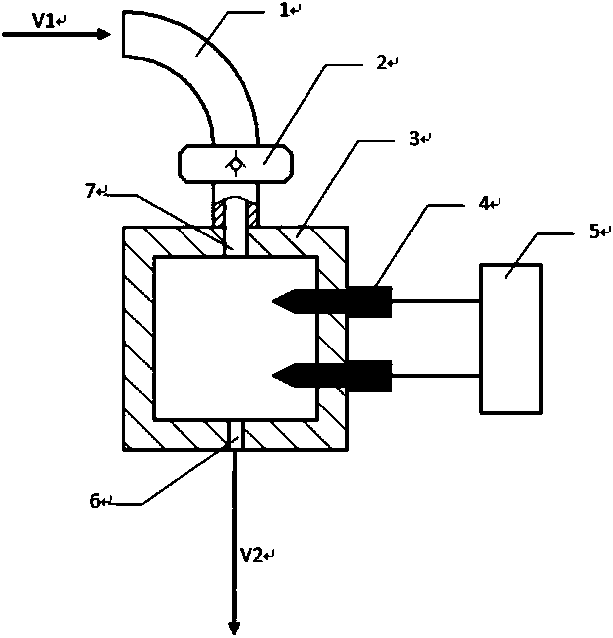
[0018] figure 1 Shown is the structural diagram of the dynamic pressure type plasma synthetic jet generator according to the present invention, including an air-inducing pipeline 1, a one-way valve 2, a generator cavity 3, a discharge electrode 4, a pulsed high-voltage power supply 5, and a jet outlet 6 and to flow into inlet 7.

[0019] The inside of the bleed air pipeline 1 is smooth, one end is connected to a small hole (not shown) arranged on the stagnation point of the leading edge, and the other end is connected to the inlet of the one-way valve 2 for introducing the future flow V1 into the one-way valve.

[0020] The inlet of the one-way valve 2 is connected to the bleed gas pipeline, and the outlet is connected to the inflow port 7 of the plasma generator, which is used to introduce the gas from the bleed gas pipeline into the generator cavity, increase the pressure in the cavity, and prevent gas backflow at the same time into the air duct.

[0021] The generator cav...


PUM


Abstract

A dynamic pressure plasma synthesis jet generator relates to a jet generating device. The device uses the dynamic pressure of the forward incoming flow to introduce a high-speed incoming flow into a plasma generator cavity through an air bleed pipeline and a one-way valve, the pressure inside the cavity is increased, and meanwhile, a high-temperature plasma is generated in the cavity through high-voltage discharge, so that the air in the cavity is subjected to thermal expansion, and a high-speed jet is generated at a jet outlet. The device is provided with a plasma generator, the air bleed pipeline, the one-way valve and a high-voltage pulse power supply, wherein the plasma generator is composed of a negative electrode, a positive electrode and a generator cavity, and the generator cavityis provided with an incoming flow inlet, the jet outlet and electrode insertion holes. The device has the advantages of simple structure, light weight, low cost, almost no influence on the aerodynamicshape of an aircraft while generating the high-speed jet, and the like. In addition, the device can also control the jet velocity within a certain range by changing the loaded electrical parameters.

Description

technical field [0001] The invention relates to a dynamic pressure plasma synthetic jet flow generator, which is a generator for generating high-speed synthetic jet flow by utilizing dynamic pressure and high temperature plasma. technical background [0002] Synthetic jets can be applied to active flow control to control flow through small-scale and localized energy injection. Compared with the traditional control technology, the active control technology using synthetic jet can carry out precise phase control on the complex dynamic process. The synthetic jet actuator is small in size, simple in structure, light in weight, and has no complicated mechanical structure. It can be arranged in various positions of various aircraft according to requirements to achieve the best control effect. [0003] The jet energy generated by the existing synthetic jet generators depends entirely on the power of the power supply. To obtain higher jet energy, a high-power power supply is requir...

Claims


Application Information

Patent Timeline
Patent Type & Authority Applications(China)
IPC IPC(8): H05H1/26
CPCH05H1/26
Inventor 林麒陈约适刘汝兵
Owner XIAMEN UNIV
Why Eureka
Try Eureka