High intensity proton cyclotron beam commissioning apparatus and beam commissioning method

A cyclotron and beam current technology, applied in DC voltage accelerators, magnetic resonance accelerators, electrical components, etc., can solve the problems of increasing labor costs and resource costs, occupying experimental sites, etc., to avoid construction and maintenance costs, and compact structure Tight, reduce the effect of occupying space

Active Publication Date: 2018-11-13
CHINA INSTITUTE OF ATOMIC ENERGY
View PDF9 Cites 0 Cited by
  • Summary
  • Abstract
  • Description
  • Claims
  • Application Information

AI Technical Summary

Problems solved by technology

Therefore, the traditional beam debugging target determines that the high-power cyclotron must build an additional beam line only for beam debugging, which not only occupies the limited experimental space around the accelerator, but also increases a lot of manpower. cost and resource cost

Method used


Image

  • High intensity proton cyclotron beam commissioning apparatus and beam commissioning method
  • High intensity proton cyclotron beam commissioning apparatus and beam commissioning method
  • High intensity proton cyclotron beam commissioning apparatus and beam commissioning method

Examples


Embodiment 1

[0040] Embodiment 1: A beam debugging target device for a high-current cyclotron, including a fixed frame that can be fixedly installed relative to the ground. The fixed frame replaces the traditional wall structure and is relatively fixedly connected to the ground. When in use, it can be set in a strong The middle of the flow cyclotron and the experimental terminal avoids the defect in the prior art that the debugging device can only be arranged at a fixed position inside the wall, so as to reduce the occupied area.

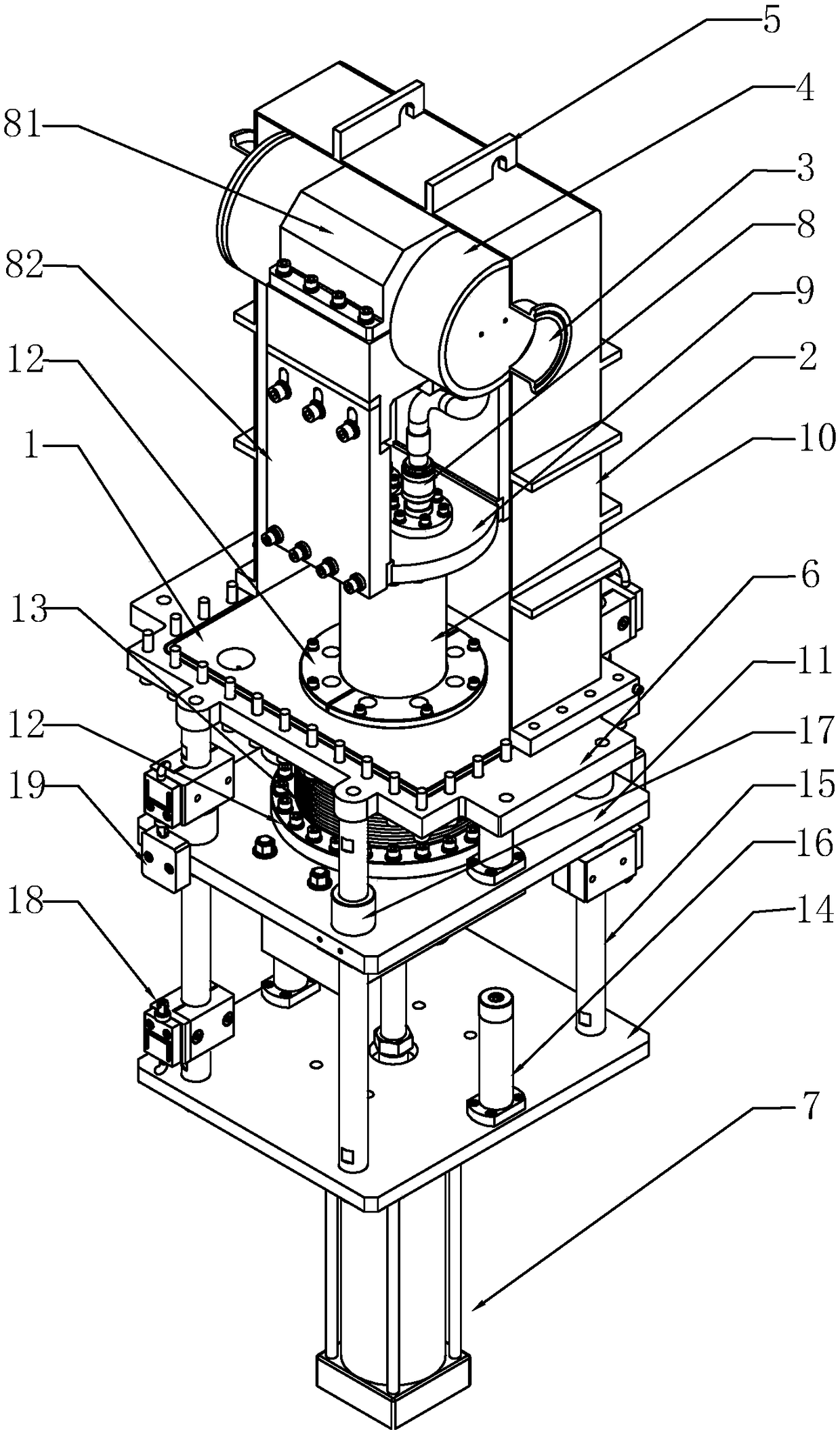
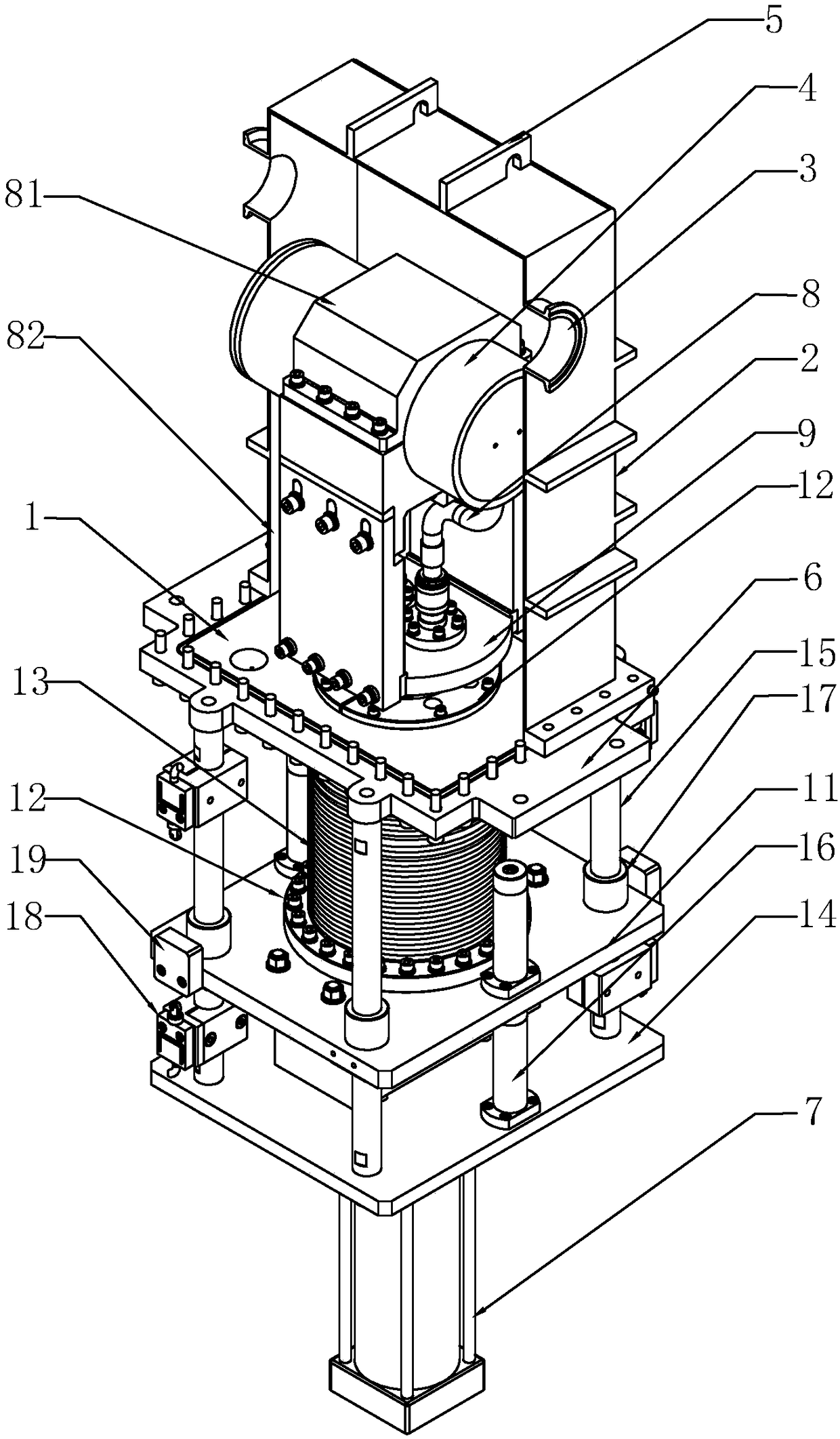
[0041] Such as figure 1 and figure 2 As shown, a first fixed plate 1 is fixedly connected to the fixed frame (not shown in the figure), and a vacuum protection cover 2 is arranged above the first fixed plate 1 (in order to show the structure in the vacuum cover, figure 1 and figure 2 The vacuum protection cover adopts a half-section structure). The vacuum protection cover 2 is provided with a beam channel 3 through which a strong proton beam passes, and a t...

Embodiment 2

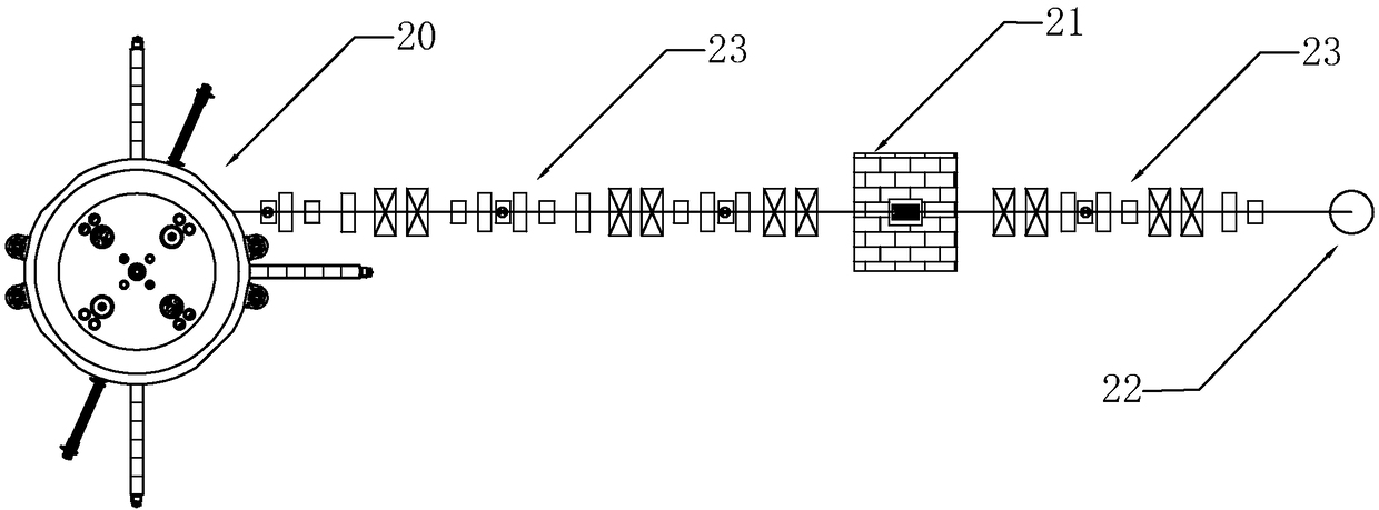
[0055] This embodiment discloses a method for debugging the beam of the high-current cyclotron described above, such as image 3 As shown, the high-current cyclotron beam debugging device 21 in Embodiment 1 is adopted, and the front end of the high-current cyclotron beam debugging device 21 is connected to the high-current cyclotron 20 through a beam vacuum pipeline 23, and the high-current cyclotron The rear end of the cyclotron beam debugging device 21 is connected to the experimental terminal 22 through a beam vacuum pipe 23, and a local shielding mechanism is set outside the high-current cyclotron beam debugging device 21. When it is necessary to perform beam debugging on the high-current cyclotron 20, the remote control starts the cylinder 7 to do the stretching movement, driving the target head 4 to rise to the beam channel 3, and the beam emitted by the high-current cyclotron 20 The streamer light will fall to the target head 4 to realize the beam adjustment process; wh...


PUM


Abstract

The invention relates to the technical field of high intensity proton cyclotron beam commissioning devices, in particular to a beam commissioning target apparatus for a high intensity proton cyclotron. The high intensity proton cyclotron beam commissioning apparatus comprises a fixed stander, wherein the fixed stander is fixedly provided with a first fixed plate, a vacuum protection cover is arranged above the first fixed plate, the vacuum protection cover is provided with a beam passage, a commissioning target head is arranged in the vacuum protection cover, an air cylinder is fixedly arranged below the first fixed plate, an intermediate assembly is arranged between the air cylinder and the target head, when the air cylinder makes the extension movement, the intermediate assembly is driven to drive the target head to move upwardly, a terminal position of the target head is just located in the beam passage, when the air cylinder makes the retraction movement, the intermediate assemblyis driven to drive the target head to move downwardly to be away from the target head, and the beam passage is communicated, so that the beam commissioning target and an experimental terminal beam line share the same beam line, and the manpower cost and the resource cost can be greatly reduced.

Description

technical field [0001] The invention relates to the technical field of beam adjustment equipment for an intense current proton cyclotron, in particular to a beam adjustment target device and a beam adjustment method for an intense current cyclotron. Background technique [0002] In recent years, high-current proton cyclotrons have been widely used in basic research of nuclear physics, material science, life science, energy, medical treatment, industry and agriculture and other disciplines and fields. The high-current cyclotron requires that the highest energy that can be emitted is 100MeV , The beam with the highest intensity current of 200μA needs a beam debugging target that can withstand the bombardment of the high-power proton beam to receive the debugging beam. The traditional high-power proton beam debugging method is to lead a beam line specially from the high-current cyclotron, install a beam debugging target at the end of the beam line, fix the high-power proton bea...

Claims


Application Information

Patent Timeline
Patent Type & Authority Applications(China)
IPC IPC(8): H05H6/00H05H13/00
CPCH05H6/00H05H13/005H05H2006/007
Inventor 宋国芳王峰刘景塬吕银龙魏素敏
Owner CHINA INSTITUTE OF ATOMIC ENERGY
Why Eureka
Try Eureka