
Motor shaft conveying line

A transmission line and motor shaft technology, applied in the field of motor shaft processing equipment, can solve problems such as high labor costs, low production efficiency, and high defect rate

Inactive Publication Date: 2018-11-16
FOSHAN CITY NANHAI POPULA FAN
View PDF9 Cites 2 Cited by
  • Summary
  • Abstract
  • Description
  • Claims
  • Application Information

AI Technical Summary

Problems solved by technology

[0002] Due to the rapid development of robots and electric vehicles, the demand for electric motors is increasing. The production of existing electric motors is labor-intensive, which causes manufacturers to bear high labor costs, and manual operations often lead to difficult quality control and production. inefficiency
[0003] The motor shaft of the motor is often the first step in motor processing, and the positioning hole on the end face of the motor shaft is the benchmark for subsequent processing. Therefore, the end face processing of the motor shaft requires high precision. The existing manual processing has a very high defect rate. height of

Method used


Image

  • Motor shaft conveying line
  • Motor shaft conveying line

Examples


Embodiment Construction

[0013] The idea, specific structure and technical effects of the present invention will be clearly and completely described below in conjunction with the embodiments and accompanying drawings, so as to fully understand the purpose, features and effects of the present invention. Apparently, the described embodiments are only some of the embodiments of the present invention, rather than all of them. Based on the embodiments of the present invention, other embodiments obtained by those skilled in the art without creative efforts belong to The protection scope of the present invention. In addition, all the connection / connection relationships mentioned in this article do not refer to the direct connection of components, but mean that a better connection structure can be formed by adding or reducing connection accessories according to specific implementation conditions. The various technical features in the present invention can be combined interactively on the premise of not confli...


PUM


Abstract

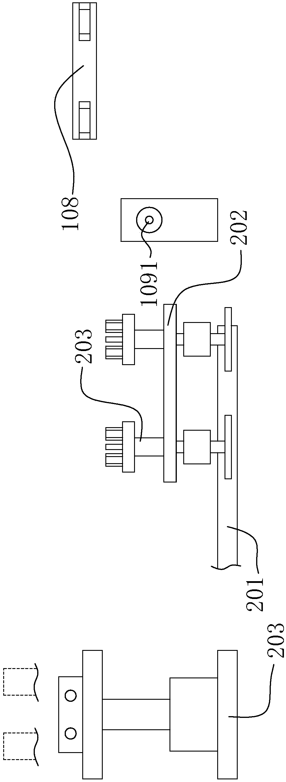
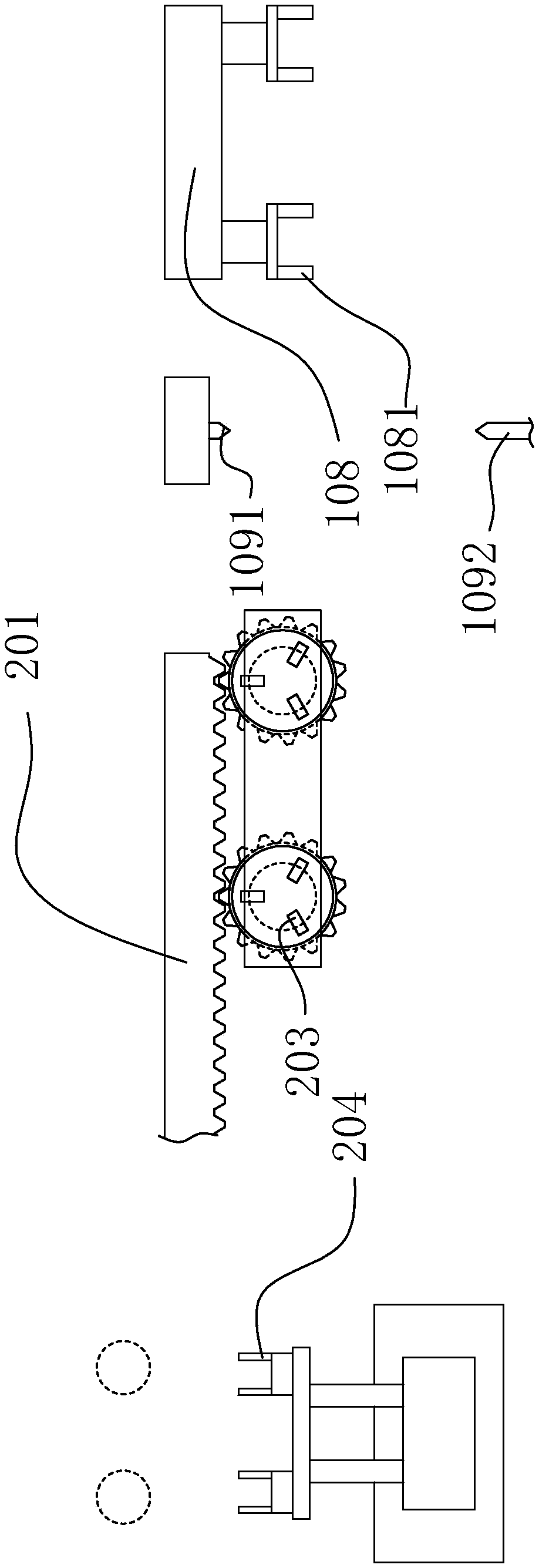
The invention discloses a motor shaft conveying line. The motor shaft conveying line comprises a shaft grabbing robot, wherein a grabbing tool is arranged on the shaft grabbing robot, a conveying frame is arranged at the left side of the shaft grabbing robot, a conveying guide rail and a centering device are arranged on the conveying frame, and the centering device comprises a location cone and apush cone; and grabbing jaws are arranged on the grabbing tool, a walking device is arranged on the conveying guide rail, a transport lifting plate is arranged on the walking device, radial clamping devices are arranged on the transport lifting plate, double-station numerically-controlled machining equipment is arranged at the front side of the conveying guide rail, a transposing device is arranged at the rear side of the conveying guide rail, and the transposing device comprises two transposing clamps. The two plate transposing clamps form one-to-one correspondence with the two radial clamping devices separately, and the left-right positions of the two plate transposing clamps are not changed in the case that motor shafts are inserted into the radial clamping devices by the plate transposing clamps and in the case that the motor shafts are taken out from the radial clamping devices by the plate transposing clamps; and in this way, accurate repeated location for the plate transposing clamps can be conveniently realized by a simple mechanical structure. The motor shaft conveying line is used for machining for the motor shafts.

Description

technical field [0001] The invention relates to motor shaft processing equipment, in particular to a motor shaft conveying line. Background technique [0002] Due to the rapid development of robots and electric vehicles, the demand for motors is increasing. The production of existing motors is labor-intensive, which leads to high labor costs for manufacturers, and manual operations often lead to difficult quality control and production. The problem of inefficiency. [0003] The motor shaft of the motor is often the first step in motor processing, but the positioning hole on the end face of the motor shaft is the benchmark for subsequent processing, so the end face processing of the motor shaft requires high precision, and the existing manual processing has a very high defect rate. height of. In the automatic production process, after the motor shaft with the end face is grabbed from the CNC machining machine, the motor shaft needs to be positioned before the automatic prod...

Claims


Application Information

Patent Timeline
Patent Type & Authority Applications(China)
IPC IPC(8): B23Q7/00B23Q7/04H02K15/00
Inventor 唐秀文徐永森
Owner FOSHAN CITY NANHAI POPULA FAN
Learn More