Spring removing mechanism

A gantry and gear shaft technology, which is used in grinding machine parts, machine tools suitable for grinding workpiece planes, grinding feed motion, etc., can solve the problem that the panel and the inner table are not coplanar, and the spring needs manual operation , can not work properly and other problems, to achieve the effect of simple structure, reduce energy consumption, reduce friction

Active Publication Date: 2018-11-16
SHAOXING JIADU SPRING MACHINE
View PDF12 Cites 0 Cited by
  • Summary
  • Abstract
  • Description
  • Claims
  • Application Information

AI Technical Summary

Problems solved by technology

The disadvantage of this method of unloading the spring is that the production efficiency is low. The second method of the existing technology: the technical solution invented by our company (patent number: ZL201110327085.0) - the shaft end at the lower end of the handle is inserted into the bearing seat at the corner of the hopper through a bearing, which can Rotate on the hopper; the panel is fixed on the handle and will swing with the rotation of the handle. There is a cone hole at one corner of the panel; the connecting rod is slidingly connected to the two control blocks on one side of the hopper. The top of the connecting rod is a conical head. The shape and position match the taper hole of the panel. The taper of the conical head is smaller than the friction self-locking angle of the steel, that is, the angle is not more than 8 degrees. The top of the conical head is provided with a rounded corner. Compression spring, the upper end of the compression spring bears against the lower end of the step, the lower end of the compression spring presses the top of the control block, the compression spring pushes the connecting rod upward, so that the conical head at the top of the connecting rod extends into the conical hole of the panel, and cooperates with the handle Fix the position of the panel, cover the panel on the hopper without shifting; the lower end of the connecting rod is pinned to the pedal, step on the pedal, the step of the connecting rod overcomes the elastic force of the compression spring and moves down, and the conical head moves down and leaves the cone on the panel. hole, the panel will swing as the handle is rotated, away from the top of the hopper
The disadvantage of this technical solution is that firstly, manual operation is required to unload the spring, which is labor-intensive, especially for large-diameter springs.
Secondly, for large-diameter springs, the mass is large, and all the spring gravity acts on the panel, resulting in a large bending moment on the handle, resulting in a large deformation, causing the panel and the inner table to be out of the same plane. When the grinding disc is swinging, the spring often The spring is stuck in the gap between the panel and the inner plate and cannot work normally

Method used


Image

  • Spring removing mechanism
  • Spring removing mechanism

Examples


Embodiment Construction

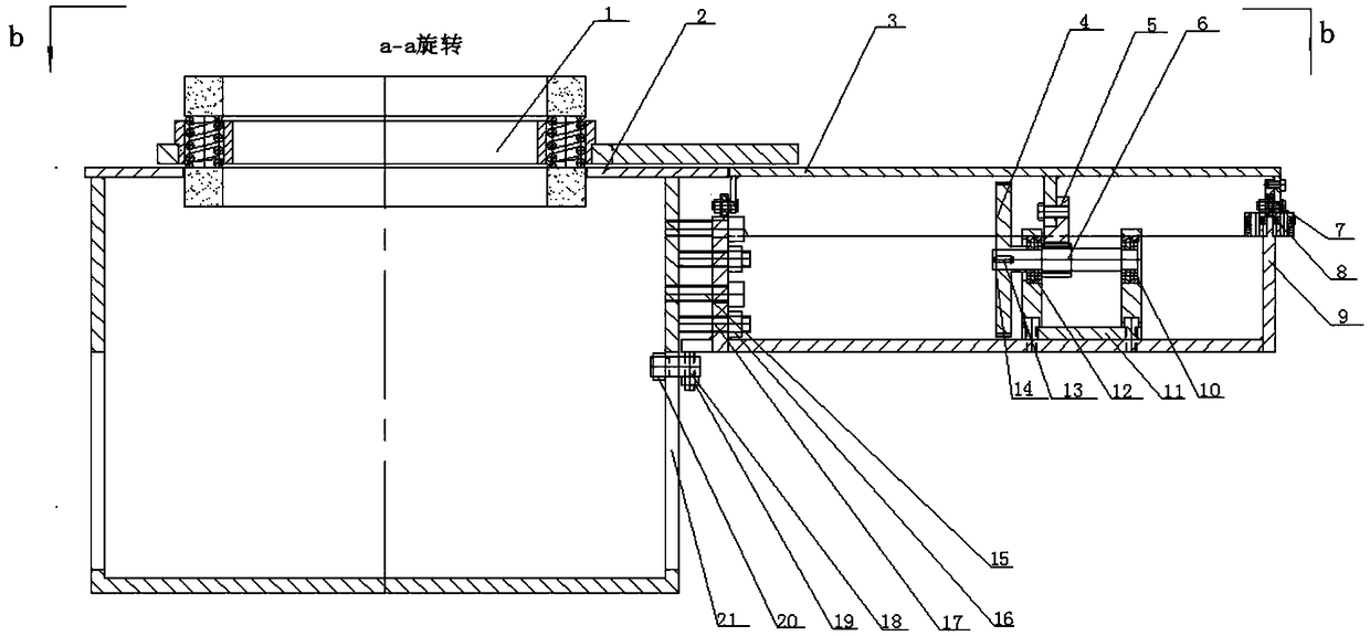
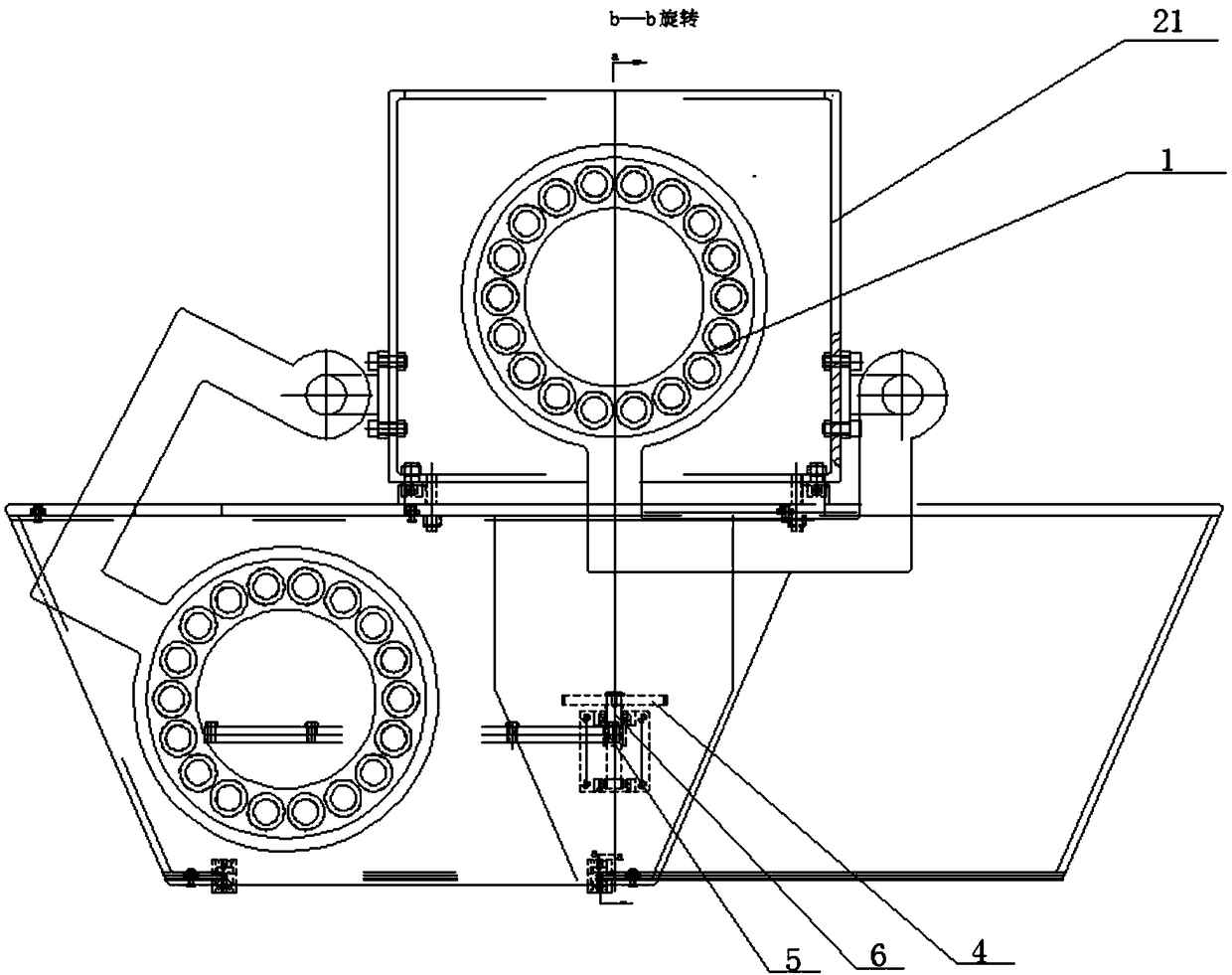
[0016] refer to Figure 1 to Figure 2 A specific embodiment of an automatic spring unloading mechanism of the present invention will be further described.

[0017] A spring unloading mechanism, comprising a box body 21, a door frame 9 is connected to the box body 21, a spring unloading door 3 is slidably connected to the door frame 9, and a bearing seat 11 is fixedly connected inside the door frame 9, The bearing seat 11 is provided with a pinion 6, the bottom of the unloading door 3 is connected with a rack 5 meshing with the pinion 6, and one end of the pinion 6 is provided with a power gear 4, and the power Gear 4 is connected with power unit, and power unit adopts motor, and power gear 4 is connected with the power shaft of motor, and motor operation drives power gear 4 to rotate, thereby drives pinion shaft 6 to rotate, because the tooth bar 5 that is fixed on unloading door 3 and The pinion shaft 6 is meshed, therefore, the pinion shaft 6 rotates to drive the rack 5 to ...


PUM


Abstract

The invention discloses a spring removing mechanism which comprises a box body. A portal is connected to the box body, a spring removing door is in sliding connection with the portal, a bearing pedestal is fixedly connected with the interior of the portal, a gear shaft is arranged in the bearing pedestal, a rack engaged with the gear shaft is connected to the bottom of the spring removing door, one end of the gear shaft is provided with a power gear, and the power gear is connected with a power device. The spring removing door is controlled by an electric device to move, the automatic removingprocess of a spring in a grinding disc can be achieved, the production efficiency of a spring grinding machine is greatly improved, the labor intensity of operators is lowered, and the problem that the spring falls down to the gap between an inner table plate and the spring removing door in a clamped mode in the grinding disc moving process to affect work is avoided by adjusting the up-down left-right gap between the spring removing door and the inner table plate.

Description

technical field [0001] The invention relates to the field of metal cutting, and more specifically relates to a spring unloading mechanism. Background technique [0002] At present, the most widely used spring is the compression spring. Usually, the two ends of the compression spring should be ground flat, and the two ends should be kept parallel so that the center line of the compression spring is perpendicular to the two ends. The common method is to grind the two ends of the compression spring with a grinding wheel. Usually, a plurality of holes are machined on the circumference of the grinding disc, and the spring is manually put into the holes. When grinding, the grinding disc rotates on a fixed axis, and the spring enters the space between the rotating upper and lower grinding wheel planes. Then, the upper grinding wheel is fed from top to bottom. When the distance between the upper and lower grinding wheels reaches the set process value, the grinding of the two ends o...

Claims


Application Information

Patent Timeline
Patent Type & Authority Applications(China)
IPC IPC(8): B24B7/17B24B41/00
CPCB24B7/17B24B41/005
Inventor 俞家林俞度
Owner SHAOXING JIADU SPRING MACHINE
Why Eureka
Try Eureka