

Electric spark machine tool grinding equipment for annular workpiece
A technology for electric discharge machine tools and ring workpieces, which is applied to machine tools designed for grinding workpiece rotating surfaces, metal processing equipment, grinding/polishing equipment, etc., and can solve problems such as high labor costs, difficult grinding, and high labor intensity , to achieve the effect of low labor cost, low grinding difficulty and low labor intensity
- Summary
- Abstract
- Description
- Claims
- Application Information
AI Technical Summary
Problems solved by technology
Method used
Image

Examples
Embodiment Construction
[0018] In order to make the technical means, creative features, goals and effects achieved by the present invention easy to understand, the present invention will be further described below in conjunction with specific illustrations.
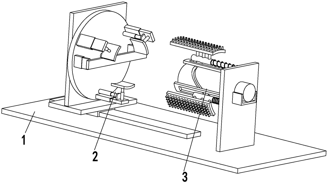
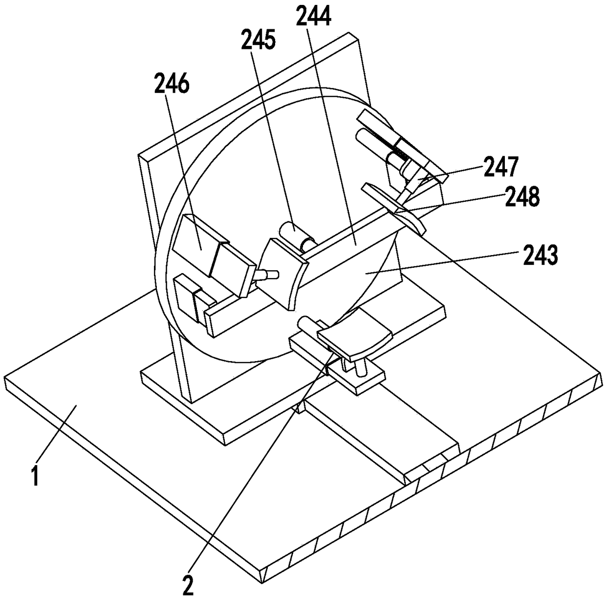
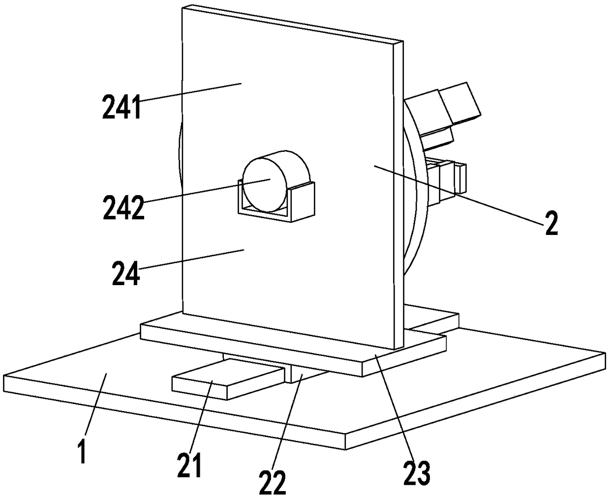
[0019] Such as Figure 1 to Figure 4 As shown, an EDM grinding device for circular workpieces includes a bottom plate 1, a fixing device 2 and an inner wall grinding device 3, and the fixing device 2 and the inner wall grinding device 3 are sequentially installed on the bottom plate 1 from left to right; in:
[0020] The inner wall grinding device 3 comprises a fixed plate 31, a rotating motor 32, a rotating column 33, a sliding block 34, a spacer 35, a telescopic rod 36, a spring 37, an adjustment cylinder 38 and a wire brush 39, and the fixed plate 31 is installed on On the bottom plate 1, a rotating motor 32 is installed on the side wall of the fixed plate 31 through a motor seat, and the output shaft of the rotating motor 32 is connected wi...
PUM
 Abstract
Description
Claims
Application Information