
Crossing operation abrasive disk structure and operation method thereof

A technology of grinding discs and grinding discs, applied in grinding tools, grinding machines, manufacturing tools, etc., can solve the problems of indistinguishable, insufficient reliability, and inconvenient replacement, and achieve the effect of improving grinding efficiency, improving replacement efficiency, and facilitating replacement.

Active Publication Date: 2018-11-16
太仓鉴崧实业有限公司
View PDF15 Cites 0 Cited by
  • Summary
  • Abstract
  • Description
  • Claims
  • Application Information

AI Technical Summary

Problems solved by technology

[0003] In addition, the grinding discs of the floor grinder are consumables and need to be replaced frequently
But at present, the existing floor grinding machine has the problem of inconvenient replacement of the grinding plate structure, and it is impossible to judge whether the grinding plate is installed in place. It is not reliable enough to judge only by human eyes.

Method used


Image

  • Crossing operation abrasive disk structure and operation method thereof
  • Crossing operation abrasive disk structure and operation method thereof

Examples


Embodiment

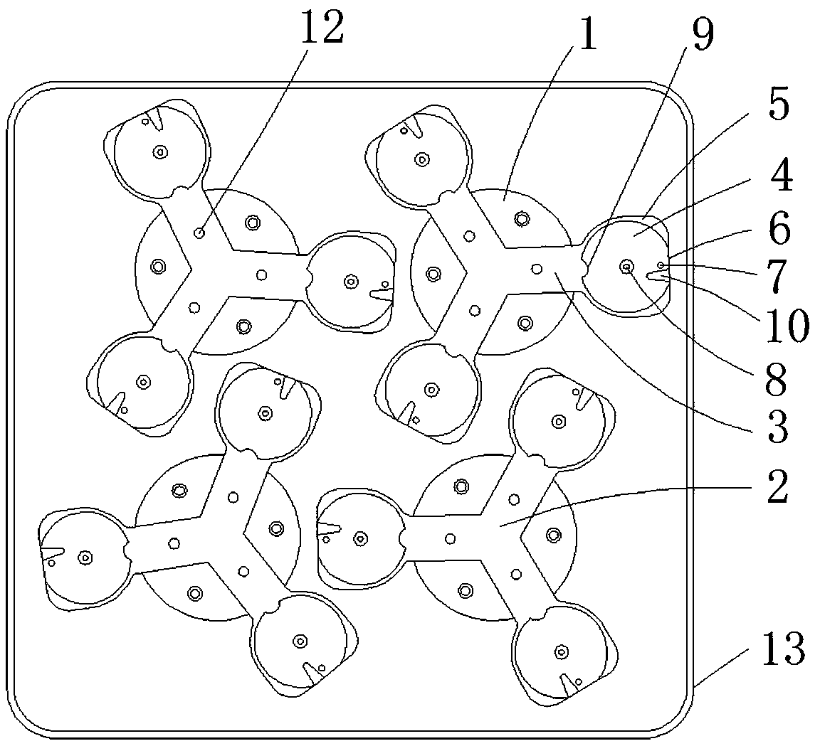
[0027] A cross-rotating millstone structure of the present invention, such as figure 1 and figure 2 As shown, it includes a set of rotating parts 1 in a rectangular array and a set of grinding discs 2 mounted on the rotating parts 1. The grinding discs 2 include a set of claws 3 in an annular array, and the claws 3 of adjacent grinding discs 2 are staggered. Setting, the end of the claw portion 3 is provided with a grinding plate installation disc 4, and the outer periphery of the grinding disc mounting disc 4 is provided with a raised wall 5, and the wall 5 is provided with a gap 6 at the end far away from the central axis of rotation of the grinding disc 2 , and, the bottom of the grinding disc mounting disc 4 is provided with a convex hull 7 at one end away from the central axis of rotation of the grinding disc 2, and the grinding disc installed in the grinding disc mounting disc 4 is provided with an escape portion corresponding to the convex protrusion 7, so A pressure ...


PUM


Abstract

The invention discloses a crossing operation abrasive disk structure and an operation method thereof and relates to the technical field of advanced manufacturing and automation. The crossing operationabrasive disk structure comprises a set of rectangular arrayed rotating parts and a set of abrasive disks mounted on the rotating parts. Each abrasive disk comprises a set of annular arrayed claw parts. The claw parts of the adjacent abrasive disks are arranged in a staggered mode. The end of each claw part is provided with an abrasive plate mounting disk. The periphery of each abrasive plate mounting disk is provided with a convex wall. The end, far away from a rotary center shaft of the corresponding abrasive disk, of each wall is provided with a notch. The end, far away from the rotary center shaft of the corresponding abrasive disk, of the bottom of each abrasive plate mounting disk is provided with a bulge, an abrasive plate mounted in each abrasive plate mounting disk is provided with an avoiding part corresponding to the bulge, the top end of each bulge is provided with a pressure sensor device, and the center of the bottom of each abrasive plate mounting disk is provided witha magnet. Through the crossing operation abrasive disk structure, the grinding efficiency is greatly improved; through attraction of the magnets and locating of the bulges, the abrasive plates are mounted firmly and are convenient to replace. The pressure sensors are used for detecting whether installation is qualified or not and the abrasive plates shift or not in the operating process, and automatic detection during the installation and operation process is realized.

Description

technical field [0001] The invention relates to the technical field of advanced manufacturing and automation, in particular to a cross-rotating grinding disc structure. Background technique [0002] The floor grinder is mainly used for ground grinding. It can effectively grind terrazzo, concrete surface, epoxy mortar layer and old epoxy floor. It has the characteristics of lightness, flexibility and high work efficiency. In the current building and construction, more and more rely on the floor grinder, and in today's high-efficiency and high-quality construction, the performance of the floor grinder, the convenience of use, and the quality of the floor grinder Construction efficiency has higher and higher requirements and expectations. [0003] In addition, the grinding discs of the floor grinder are consumables and need to be replaced frequently. But at present, the grinding plate structure of the existing floor grinder has the problem of inconvenient replacement, and it...

Claims


Application Information

Patent Timeline
Patent Type & Authority Applications(China)
IPC IPC(8): B24B37/16B24B37/34B24B7/18
CPCB24B7/186B24B37/16B24B37/345Y02P70/10
Inventor 邹立伟
Owner 太仓鉴崧实业有限公司
Learn More