Suspended type railway vehicle

A rail vehicle and suspension technology, which is applied in the field of rail transit, can solve problems such as inconvenience, and achieve the effects of simple structure, convenient handling of people getting on and off and faults, and shortening the construction period

Pending Publication Date: 2018-11-16
JIANGSU FLYING SHUTTLE INTELLIGENT CO LTD
View PDF0 Cites 5 Cited by
  • Summary
  • Abstract
  • Description
  • Claims
  • Application Information

AI Technical Summary

Problems solved by technology

[0003] In order to solve the inconvenient problem in the current overhead rail transit system, the way of getting on and off the rail car and fault maintenance can only rely on the way of stopping the platform or lowering the track, the present invention provides a suspended rail vehicle, including a running mechanism 2. A car body 3 is connected to the bottom of the walking mechanism 2 through the lifting mechanism, so that people only need to lower the car body when getting on and off and troubleshooting

Method used


Image

  • Suspended type railway vehicle
  • Suspended type railway vehicle
  • Suspended type railway vehicle

Examples


Embodiment 1

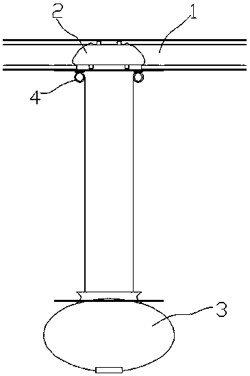
[0031] Such as figure 1 The suspended rail vehicle shown includes a running gear 2 on a track 1, and a car body 3 is connected with a lifting mechanism below the running gear 2, so that people only need to lower the car body when getting on and off and troubleshooting. The lifting mechanism includes a power unit 4 capable of making the car body lift. The upper end of the power unit 4 is connected to the running mechanism 2 and the lower end is connected to the car body 3 . The power unit 4 is a hoist, and the hoist is arranged on the bottom of the running mechanism 2, and the end of the steel cable in the hoist is connected with the car body 3. Above-mentioned winch also can replace with hydraulic cylinder, and hydraulic cylinder can make car body 3 lifting as power equally.

Embodiment 2

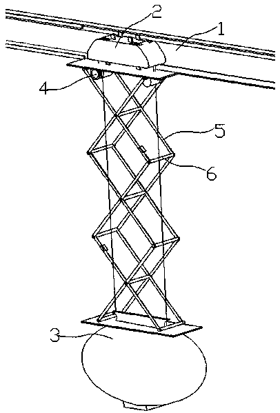
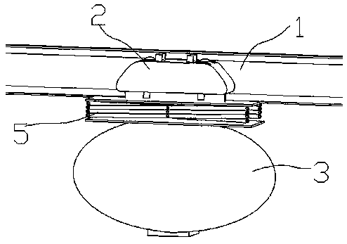
[0033] Such as figure 2 and image 3 As shown, in this embodiment, on the basis of Embodiment 1, an anti-sway stabilizing device is connected between the running mechanism 2 and the car body 3, and the anti-swaying stabilizing device is mainly composed of two parallel telescopic grids 5, The upper ends of the two telescopic grids 5 are connected to the running mechanism 2, and the lower ends are connected to the car body 3. The nodes of the two telescopic grids 5 correspond to each other, and a cross bar 6 is connected between the corresponding two nodes. The two ends pass through two corresponding nodes, and can also be rotated at the nodes, so that the device can not only expand and contract, but also the telescopic grid can prevent wind in the longitudinal direction, and the crossbar can play the role of lateral support, so that it achieves a relatively Good windproof and anti-shake effect.

Embodiment 3

[0035] Such as Figure 4 As shown, in this embodiment, on the basis of Embodiment 1, an anti-sway stabilizing device is connected between the traveling mechanism 2 and the vehicle body 3. The anti-swaying stabilizing device includes four sets of slide plates 7, and the four sets of slide plates 7 are respectively arranged on Around the car body 3, each group of slide plates 7 includes at least two, and the numbers are equal.

[0036] Such as Figure 5 As shown, the rear side of the slide plate 7 is provided with an inwardly recessed longitudinal chute 72, and the front side is provided with a slider 71, as Figure 6 Shown, the slide block 71 of the last slide plate can slide in the chute 72 of the previous slide plate, the upper end of the front slide plate 7 is connected with the running gear 2, and the lower end of the last slide plate 7 is connected with the car body 3. The design of four sets of skateboards also makes it better for windproof and anti-shake effect. The u...


PUM


Abstract

The invention discloses a suspended type railway vehicle. The railway vehicle includes a walking mechanism, and a vehicle body is connected to the lower portion of the walking mechanism through a lifting mechanism. The vehicle body is driven to ascend and descend by the lifting mechanism to adapt to the height of a ground station; compared with an existing mode of lifting a station and lowering arailway, the suspended type railway vehicle has the advantages of being much simpler and capable of making it more convenient to get on or off the vehicle and deal with errors. Moreover, the structureof the lifting mechanism is also much simpler, and the construction cycle is greatly shortened. Since the vehicle body can ascend and descend, passengers can get one or off the vehicle at anytime, the vehicle body can still land on the ground through the lifting mechanism if an error occurs during running, and therefore the passengers can safely escape.

Description

technical field [0001] The invention relates to the field of rail transportation, in particular to a suspended rail vehicle. Background technique [0002] For overhead rail transit systems such as light rail, cloud rail, and suspended rail transit systems, there are problems with rail car stops and rail car fault handling. Conventional stops mainly rely on the establishment of high-rise platforms protruding from the ground, by raising the height of the platform to adapt to the height of the track, and there are also solutions to reduce the height of the track to adapt to the ground platform. However, the structure of the platform that can be raised and the track that can be lowered is complicated, and the construction time is long, and there are many structures that need to be associated with raising the platform and lowering the height of the track, and the operation is also quite complicated. In addition, due to the limitation of conditions, the existing rail cars can onl...

Claims


Application Information

Patent Timeline
Patent Type & Authority Applications(China)
IPC IPC(8): B61B3/00B61B1/02E01B25/24
CPCB61B1/02B61B3/00E01B25/24
Inventor 胡震何先志
Owner JIANGSU FLYING SHUTTLE INTELLIGENT CO LTD
Why Eureka
Try Eureka