Electromagnetic clutch brake

An electromagnetic clutch and brake technology, applied in the direction of magnetic drive clutches, clutches, non-mechanical drive clutches, etc., can solve the problems of inability to automatically control and remote operation, large size of clutch brakes, endangering equipment and personal safety, etc. Control the effect of remote operation, compact structure and long service life

Pending Publication Date: 2018-11-16
SHAOXING IND SCI DESIGN & RES INST CO LTD
View PDF1 Cites 0 Cited by
  • Summary
  • Abstract
  • Description
  • Claims
  • Application Information

AI Technical Summary

Problems solved by technology

For example, the torque transmission effect of the paper cutter clutch is related to the cutting force of the cutter. If the friction of the clutch friction plate is insufficient, the torque transmission is poor, the clutch slips, the cutting force of the cutter decreases, and the paper pier cannot be cut through. It will cause the product to be scrapped; if the braking force of the brake is insufficient, or the response speed is slow, the cutter bed of the paper cutter cannot stop immediately, which will endanger the safety of equipment and personal
[0003] Chinese Invention Patent No. ZL201310525866.X discloses a "clutch brake" structure; it includes an input shaft, an output shaft, and an output shaft sleeve. The external splines of the output shaft are meshed; the active top spline teeth of the input shaft and the driven separation top spline teeth of the output shaft correspond to the convex and concave points of the active top and driven separation top respectively; its characteristics are: avoiding the use of electricity or The defect of electro-hydraulic drive eliminates the cost increase caused by wiring, reduces the difficulty of mechanism design, has low noise and wear, and has a longer service life; it is convenient to disassemble and adjust, and easy to maintain; the sealing effect is good, and the lubrication points are well lubricated ; Its disadvantages are: (1) The clutch brake is a purely mechanical brake with slow response speed, cannot ensure accurate combination in a very short time, and cannot be automatically controlled and operated remotely; (2) The clutch brake is relatively small in size. Large, complex structure, large floor space, inconvenient installation and maintenance; a clutch brake with fast response, large braking torque, good torque transmission, and no slippage of the clutch has not yet been developed.

Method used


Image

  • Electromagnetic clutch brake
  • Electromagnetic clutch brake
  • Electromagnetic clutch brake

Examples


Embodiment

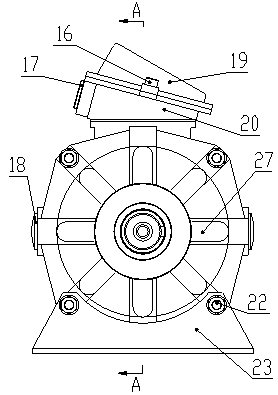
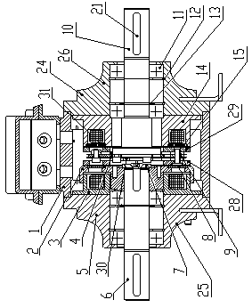
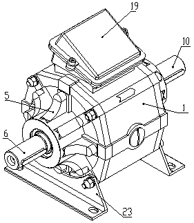
[0032] Such as figure 1 , figure 2 , image 3 , Figure 4 , Figure 5 , Figure 6 , Figure 7 , Figure 8 and Figure 9 As shown, the electromagnetic clutch brake provided by this embodiment includes a hollow cylindrical box body, a clutch body and a brake body are fixedly arranged at the left and right ends of the box body, an intermediate combination is arranged between the clutch body and the brake body, and the top of the box body The junction box seat is fixedly installed, and the junction box cover is fixedly installed on the top of the junction box seat. The junction box cover is fixed on the junction box seat by screws. The wiring device is connected; the installation base is fixed under the clutch body and the brake body, and the base is fixed under the clutch body and the brake body by bolts, which is convenient for the installation of the electromagnetic clutch and brake.

[0033] Such as figure 2 As shown, the clutch body includes a clutch end cover, the c...


PUM


Abstract

The invention discloses an electromagnetic clutch brake. The electromagnetic clutch brake comprises a hollow cylindrical box body, a clutch body and a brake body are fixedly arranged at the left end and the right end of the box body, an intermediate body combination is arranged between the clutch body and the brake body, and a junction box seat is fixedly arranged above the box body; a junction box cover is fixedly installed above the junction box seat, the junction box cover is fixed on the junction box seat through screws, and a wire passing screw sleeve is arranged on one side of the junction box seat; and a base is fixedly installed below the clutch body and the brake body, and the base is fixed below the clutch body and the brake body through bolts. The structure is simple and compact, the operation is simple and convenient, and accurate combination can be guaranteed within extremely short time; moreover, connection is reliable, braking is flexible, and automatic control and long-distance operation of a working mechanism can be realized; and due to a structure that a clutch rotating disc drives a clutch friction plate to rotate is adopted, so that the abrasion is reduced, thepower supply of a coil is reliable and timely, the control power is small, and the service life is long.

Description

technical field [0001] The invention belongs to the technical field of braking devices, and relates to an electromagnetic clutch brake. Background technique [0002] For some moving machines that need to accurately control the time and position state, the clutch brake is usually used for transmission. When the machine needs to move, the clutch is combined to transmit the driving force of the driver to the machine to make it move; when the machine needs to stop, the clutch is separated and the brake is combined to overcome the inertia of the machine and stop it immediately. The torque transmission effect of the clutch directly affects the power transmission efficiency of the machine; the braking force and response speed of the brake directly affect the time and position control accuracy of the mechanical movement, and become an important technical index of the mechanical device. For example, the torque transmission effect of the paper cutter clutch is related to the cutting ...

Claims


Application Information

Patent Timeline
Patent Type & Authority Applications(China)
IPC IPC(8): F16D67/06F16D27/112
CPCF16D67/06F16D27/112
Inventor 黄叶红张永明
Owner SHAOXING IND SCI DESIGN & RES INST CO LTD
Why Eureka
Try Eureka