Insulation structure for dry-type transformer
A technology of dry-type transformer and insulation structure, which is applied in the direction of transformer/inductor parts, transformer/inductor coil/winding/connection, prevention/reduction of unnecessary electric/magnetic influence, etc., and can solve the main airway distance Large, thick resin layer, unreliable insulation and other problems, to achieve the effect of improving product reliability, good practicability, and reducing costs
- Summary
- Abstract
- Description
- Claims
- Application Information
AI Technical Summary
Problems solved by technology
Method used
Image
Examples
Embodiment 1
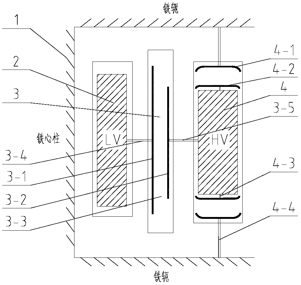
[0019] Such as figure 1 As shown, the transformer in the embodiment of the present invention is similar to the existing transformer in its basic structure and components, including the core 1 (including the core column and the iron yoke), the low-voltage winding 2 sleeved on the outside of the core 1 (core column), and the low-voltage The high-voltage winding 4 outside the winding; the low-voltage winding 2 and the low-voltage winding 4 are all encapsulated and cured by epoxy resin. The insulation structure of the embodiment of the present invention is as follows: a first insulation device 3 is arranged between the low voltage winding 2 and the high voltage winding 4; The insulating device and the high-voltage winding 4 are integrally cast, which are not marked independently in the figure).
[0020] The cylindrical first insulating device 3 according to the embodiment of the present invention is provided with a first shielding layer 3-1 near the inner wall and a second shield...
Embodiment 2
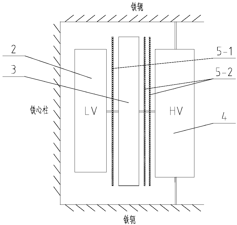
[0025] The structure of this embodiment is similar to that of the above-mentioned embodiment 1, the difference is that this embodiment can be used with an insulating cylinder according to the requirement of withstand voltage to increase the insulation reliability. Such as figure 2 As shown, a first insulating barrel 5-1 is set between the low voltage winding 2 and the first insulating device 3; a second insulating barrel 5-2 is set between the first insulating device 3 and the high voltage winding 4; wherein, the insulating barrel can Set to 1~3 as needed.
Embodiment 3
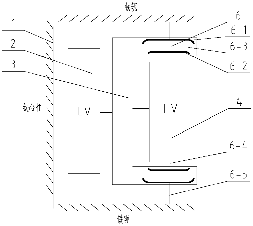
[0027] This embodiment is derived from Embodiment 1. The difference in structure from Embodiment 1 is that the second insulating device and the high-voltage winding 4 in Embodiment 1 are separately formed. To show the difference, this embodiment is called the first Three insulating devices6. In this embodiment, a third insulating device 6 is provided at the upper and lower ends of the high voltage winding 4 . Similar to the first insulating device 3, the third insulating device 6 is provided with a fifth shielding layer 6-1 and a sixth shielding layer 6-2 on the upper and lower sides respectively, and connects the ends of the high voltage winding 4 to the The core 1 (iron yoke) is connected to the fifth shielding layer 6-1 through the sixth connecting line 6-5 to form an equipotential. The inner wall of the third insulating device 6 is in contact with the first insulating device 3 , and the joint between the two is sealed with a sealing ring.
PUM
| Property | Measurement | Unit |
|---|---|---|
| thickness | aaaaa | aaaaa |
Abstract
Description
Claims
Application Information
 - R&D
- Intellectual Property
- Life Sciences
- Materials
- Tech Scout
- Unparalleled Data Quality
- Higher Quality Content
- 60% Fewer Hallucinations
Browse by: Latest US Patents, China's latest patents, Technical Efficacy Thesaurus, Application Domain, Technology Topic, Popular Technical Reports.
© 2025 PatSnap. All rights reserved.Legal|Privacy policy|Modern Slavery Act Transparency Statement|Sitemap|About US| Contact US: help@patsnap.com


