A dry-type transformer insulation structure

A technology of dry-type transformer and insulation structure, which is applied to the parts of transformer/inductor, transformer/inductor coil/winding/connection, circuit, etc., which can solve the problem of large distance between main channels, thick resin layer, and unreliable insulation and other issues to achieve the effect of improving product reliability, good practicability, and reducing costs

Active Publication Date: 2019-11-22
JIANGSU HONGYUAN ELECTRIC +2
View PDF6 Cites 1 Cited by
  • Summary
  • Abstract
  • Description
  • Claims
  • Application Information

AI Technical Summary

Problems solved by technology

[0003] Purpose of the invention: In order to overcome the shortcomings of the prior art, the purpose of the present invention is to provide a new type of insulation structure for dry-type transformers to solve the problems of large main channel distance and air gaps in the structure of high-voltage (above 35kV) dry-type transformers. The insulation is unreliable for the main insulation medium, and the thickness of the resin layer of the winding is too thick and easy to crack.

Method used


Image

  • A dry-type transformer insulation structure
  • A dry-type transformer insulation structure
  • A dry-type transformer insulation structure

Examples


Embodiment 1

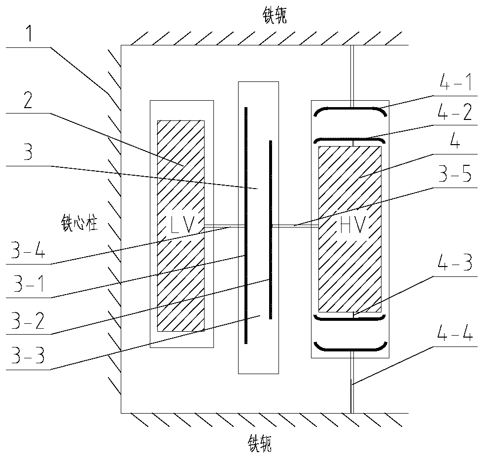
[0019] Such as figure 1 As shown, the transformer in the embodiment of the present invention is similar to the existing transformer in its basic structure and components, including the core 1 (including the core column and the iron yoke), the low-voltage winding 2 sleeved on the outside of the core 1 (core column), and the low-voltage The high-voltage winding 4 outside the winding; the low-voltage winding 2 and the low-voltage winding 4 are all encapsulated and cured by epoxy resin. The insulation structure of the embodiment of the present invention is as follows: a first insulation device 3 is arranged between the low voltage winding 2 and the high voltage winding 4; The insulating device and the high-voltage winding 4 are integrally cast, which are not marked independently in the figure).

[0020] The cylindrical first insulating device 3 according to the embodiment of the present invention is provided with a first shielding layer 3-1 near the inner wall and a second shield...

Embodiment 2

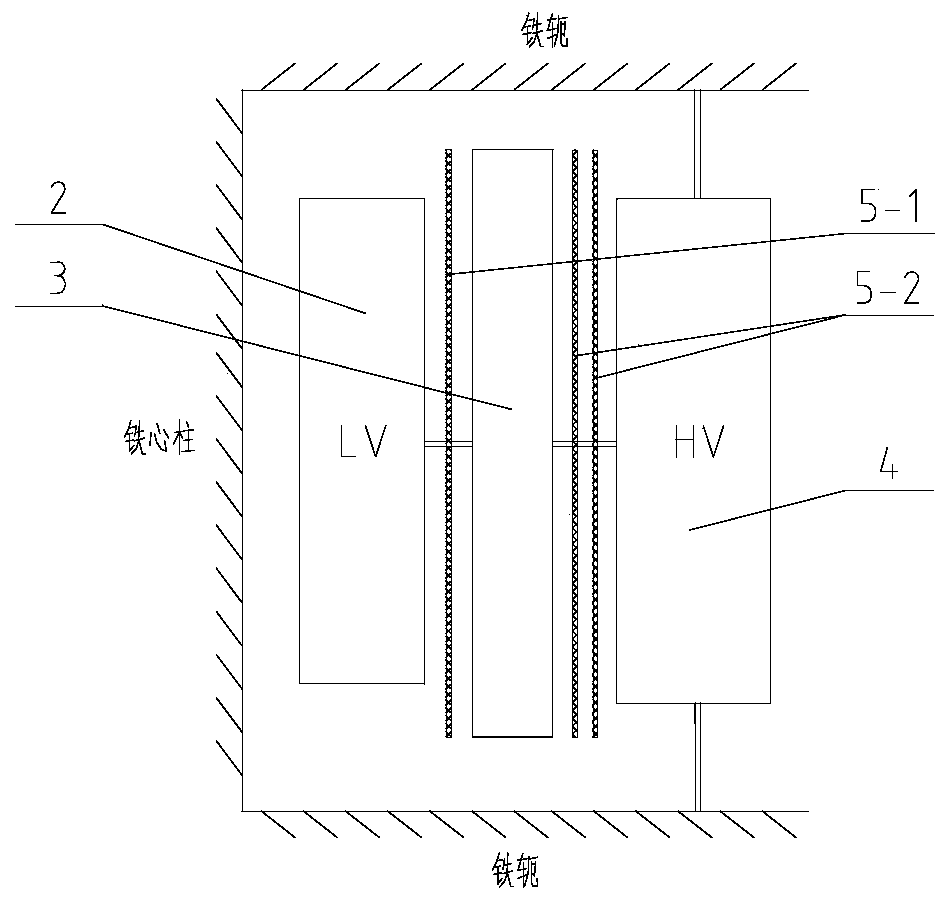
[0025] The structure of this embodiment is similar to that of the above-mentioned embodiment 1, the difference is that this embodiment can be used with an insulating cylinder according to the requirement of withstand voltage to increase the insulation reliability. Such as figure 2 As shown, a first insulating barrel 5-1 is set between the low voltage winding 2 and the first insulating device 3; a second insulating barrel 5-2 is set between the first insulating device 3 and the high voltage winding 4; wherein, the insulating barrel can Set to 1~3 as needed.

Embodiment 3

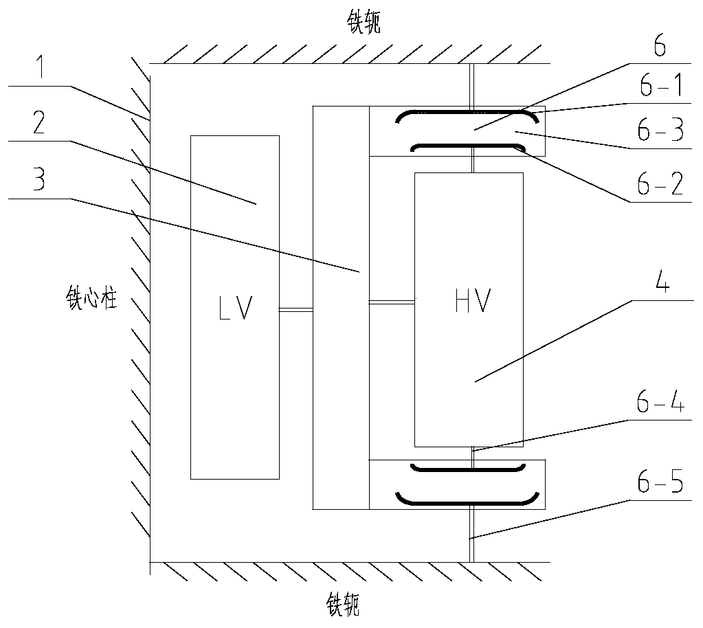
[0027] This embodiment is derived from Embodiment 1. The difference in structure from Embodiment 1 is that the second insulating device and the high-voltage winding 4 in Embodiment 1 are separately formed. To show the difference, this embodiment is called the first Three insulating devices6. In this embodiment, a third insulating device 6 is provided at the upper and lower ends of the high voltage winding 4 . Similar to the first insulating device 3, the third insulating device 6 is provided with a fifth shielding layer 6-1 and a sixth shielding layer 6-2 on the upper and lower sides respectively, and connects the ends of the high voltage winding 4 to the The core 1 (iron yoke) is connected to the fifth shielding layer 6-1 through the sixth connecting line 6-5 to form an equipotential. The inner wall of the third insulating device 6 is in contact with the first insulating device 3 , and the joint between the two is sealed with a sealing ring.


PUM

PropertyMeasurementUnit
thicknessaaaaaaaaaa

Abstract

The invention discloses an insulation structure suitable for a dry-type transformer with the voltage grade of 35 kV or above. A first cylindrical insulation device is arranged between a low-voltage winding and a high-voltage winding of the dry-type transformer, and a second annular cake-shaped second insulation device is also arranged at the end of the high-voltage winding. Shielding layers are arranged on the portions, close to the inner wall and the outer wall, of the first insulation device respectively, and the shielding layers are connected with the middle of the low-voltage winding and the middle of the high-voltage winding respectively to form equipotential. Shielding layers are arranged on the portions, close to the upper wall and the lower wall, of the second insulation device respectively, and the shielding layers are connected with the high-voltage winding and an iron yoke of an iron core respectively to form equipotential. Therefore, the second insulation device becomes a main bearing unit of the voltage at the end of the high-voltage winding. The insulation structure solves the problems that according to the structure of a high-voltage dry-type transformer, the main air channel distance is large, insulation is not reliable due to the fact that air serves as a main insulation medium, and cracking is likely to occur because the thickness of a resin layer of a windingis too large, and has the advantages of being good in practicability and reliability and capable of reducing the cost.

Description

technical field [0001] The invention relates to a power transformer, in particular to an insulation structure of a dry-type transformer, which is suitable for the design of the insulation structure of a high-voltage dry-type transformer, and is applied in power transmission and distribution, chemical industry, building materials and other places. Background technique [0002] Oil-immersed transformers are ideal substitutes for oil-immersed transformers due to oil leakage pollution and flammable and explosive properties. Due to the characteristics of solid-gas mixed insulation of dry-type transformers, its insulation structure is more stringent than that of oil-immersed transformers. The higher the voltage level, the more difficult the insulation is, especially the air gap insulation between high-voltage windings and low-voltage windings. The control of insulation distance and cost becomes a contradiction. Contents of the invention [0003] Purpose of the invention: In ord...

Claims


Application Information

Patent Timeline
Patent Type & Authority Patents(China)
IPC IPC(8): H01F27/28H01F27/32H01F27/36
CPCH01F27/2828H01F27/324H01F27/325H01F27/36
Inventor 张志立潘有龙赵仰东黄健柳涛吴夕科邵传益杨文清赵祖祥刘青云
Owner JIANGSU HONGYUAN ELECTRIC
Why Eureka
Try Eureka