Current waveform real-time monitoring-based power system

A current waveform, real-time monitoring technology, applied in system integration technology, information technology support system, electrical components, etc., can solve problems such as power loss and loss, and achieve the effect of reducing harmonic elimination equipment, facilitating monitoring, and improving voltage qualification rate

Inactive Publication Date: 2018-11-16
张作夷
View PDF10 Cites 2 Cited by
  • Summary
  • Abstract
  • Description
  • Claims
  • Application Information

AI Technical Summary

Problems solved by technology

In the process of power transmission, power transformation and power distribution, there are power losses and losses

Method used


Image

  • Current waveform real-time monitoring-based power system

Examples


Embodiment

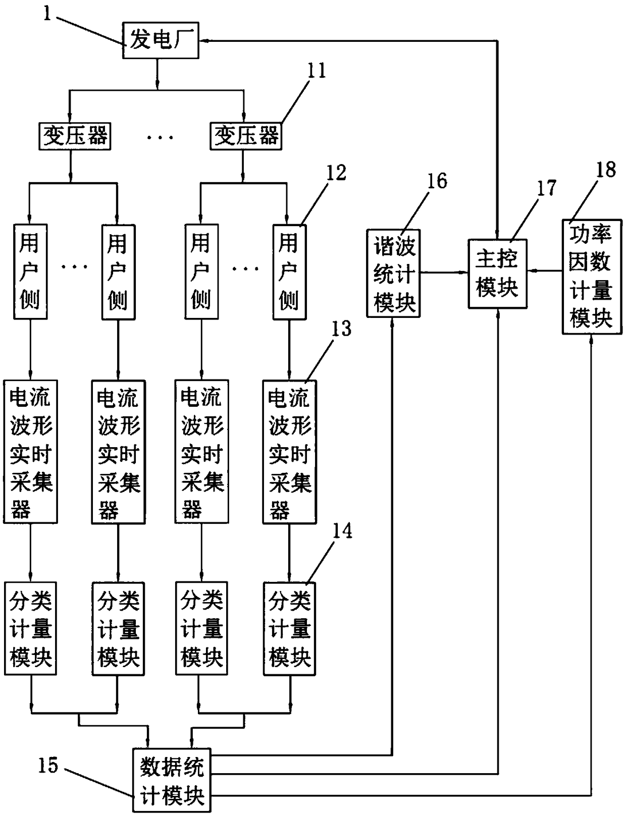
[0029] Embodiment: Power system based on current waveform real-time monitoring, such as figure 1 As shown, it includes a power plant 1 , a transformer 11 and a user side 12 , the power plant 1 is provided with at least one transformer 11 , and each transformer 11 is correspondingly provided with at least one user side 12 . It also includes a current waveform real-time collector 13 , a classification and metering module 14 , a data statistics module 15 and a main control module 17 . The current waveform real-time collector 13 communicates with the classification and metering module 14, and is used to collect the electric energy parameters of the user side 12 and transmit the electric energy parameters to the classification and metering module 14. The electric energy parameters include but not limited to current, voltage and power. The classification and metering module 14 is connected with the data statistics module 15 in communication, and is used to perform load classificatio...


PUM


Abstract

The invention discloses a current waveform real-time monitoring-based power system, relates to the technical field of power distribution systems and aims at solving the problem of power loss caused byan estimation error in the reactive compensation process due to the fact that a certain error exists in a reactive compensation capacity value obtained through estimation. According to the main points of the technical scheme, the power system comprises a power plant, at least one transformer, at least one user side, a current waveform real-time collector, a classification and measurement module,a data statistics module and a master control module, wherein the current waveform real-time collector is in communication connection with the classification and measurement module; the classificationand measurement module is in communication connection with the data statistics module; the data statistics module is in communication connection with the master control module; and the master controlmodule is in communication connection with the transformers. The current waveform real-time monitoring-based power system has the effects of accurately analyzing and calculating the reactive compensation capacity and improving the power quality.

Description

technical field [0001] The invention relates to the technical field of power distribution systems, more specifically, it relates to a power system based on real-time monitoring of current waveforms. Background technique [0002] The power system is an electric energy production and consumption system composed of power plants, power transmission and transformation lines, power supply and distribution stations, and power consumption. Its function is to convert the primary energy in nature into electric energy through the power generation device, and then supply the electric energy to various users through power transmission, transformation and distribution. In the process of power transmission, power transformation and power distribution, there are power losses and losses. The loss rate of electric energy reflects the main economic and technical indicators of power network planning and design, production operation and management level. [0003] The power loss in the existing...

Claims


Application Information

Patent Timeline
Patent Type & Authority Applications(China)
IPC IPC(8): H02J13/00H02J3/18
CPCH02J13/0006H02J3/18Y02E40/30Y02E40/70Y04S10/22Y04S10/52
Inventor 张作夷石开明
Owner 张作夷
Why Eureka
Try Eureka