LED driving energy-saving power source with function of overvoltage protection

A LED drive and overvoltage protection technology, applied in the direction of electric light source, electroluminescent light source, light source, etc., can solve the problems of reducing maintenance cost, LED drive power cannot be self-recovery, etc., to achieve the effect of reducing maintenance cost and enhancing utilization rate

Active Publication Date: 2018-11-16
FOSHAN LAMDEN ELECTRONICS LIGHTING CO
View PDF4 Cites 0 Cited by
  • Summary
  • Abstract
  • Description
  • Claims
  • Application Information

AI Technical Summary

Problems solved by technology

[0005] The object of the present invention is to provide an energy-saving LED drive power supply with overvoltage protection. By connecting an overvoltage protection circuit composed of a resistor, a trigger tube and a triac between the mains input circuit and the choke coil T1, When the voltage connected to the mains input circuit is too high, the voltage obtained by the resistor divider disconnects a bidirectional thyristor, thereby disconnecting the power supply from the mains voltage to the subsequent circuit. When the mains voltage returns to normal , after the voltage obtained by resistor division returns to normal, a two-way thyristor is turned on, and the mains voltage is supplied to the following drive circuit again through the two-way thyristor, and the whole circuit returns to normal operation, which is convenient for effective protection of the circuit at the same time The self-recovery of the circuit is realized, the maintenance cost is reduced, and the problem that the existing LED drive power cannot be self-recovery after overvoltage protection is solved

Method used


Image

  • LED driving energy-saving power source with function of overvoltage protection
  • LED driving energy-saving power source with function of overvoltage protection

Examples


specific Embodiment 1

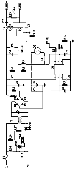
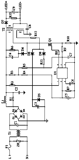
[0024] see figure 1 As shown, the present invention is an LED-driven energy-saving power supply with overvoltage protection, including: mains input circuit, overvoltage protection circuit, rectifier bridge, drive chip U1, power switch tube Q1, NPN transistor Q2, switching transformer T2 and the power supply output terminal; the mains input circuit is connected to the driver chip U1 through the overvoltage protection circuit and the rectifier bridge in turn; the driver chip U1 is connected to the power supply output terminal through the power switch tube Q1 and the switching transformer T2 in turn; the driver chip U1 is connected to the power supply output terminal through the NPN Transistor Q2 is connected to switching transformer T2; overvoltage protection circuit includes resistors R14, R15, R16, R17, trigger tube DS1 and bidirectional thyristor VS1, VS2; resistor R14 is connected in series with resistor R15, resistor R16 and resistor R17 are connected in series Connected i...

specific Embodiment 2

[0033] When the power switch tube Q1 is turned off, when the induction current of the switching transformer T2 coil 2 becomes small, the function of the NPN transistor Q2 is the function of the transistor itself, and the voltage in the filter capacitor C3 can be controlled with a small Ib current to pass through the NPN transistor Q2 Send the zero current detection signal to pin 5 of the driver chip U1. The voltage value of the zero-current detection signal on pin 5 of the driver chip U1 is 0.35V, that is, when the voltage of the zero-current detection signal is greater than 0.35V, the power switch tube Q1 is turned off, and the induced voltage of the switching transformer T2 coil 3 can continue to be sent to the load . Once the voltage of the zero-current detection signal is equal to 0.35V, the power switch tube Q1 will be turned on again, and the coil 3 of the switching transformer T2 will immediately terminate the power supply to the load.

specific Embodiment 3

[0034] The overvoltage protection self-recovery circuit is composed of resistors R14, R15, R16, R17, trigger tube DS1 and bidirectional thyristor VS1, VS2. When the input mains voltage is normal, the resistors R16 and R17 supply the gate voltage of the bidirectional thyristor VS2, the bidirectional thyristor VS2 is normally turned on, and the mains voltage is supplied to the driving circuit behind through the bidirectional thyristor VS2, the whole circuit normal work. The voltage divided by the resistors R14 and R15 is not enough to turn on the trigger tube DS1, the trigger tube DS1 is in the off state, the triac VS1 is also in the off state, and has no effect on the triac VS2. When the input mains voltage is too high and reaches 280V, the voltage obtained by dividing the resistor R14 and resistor R15 will turn on the trigger tube DS1, and the trigger tube DS1 will be turned on to supply the gate voltage of the bidirectional thyristor VS1. SCR VS1 is turned on. After the bid...


PUM


Abstract

The invention, which relates to the technical field of LED driving power sources, discloses an LED driving energy-saving power source with the function of overvoltage protection. The LED driving energy-saving power source comprises a commercial power input circuit, an overvoltage protection circuit, a rectifier bridge, a driving chip U1, a power switch tube Q1, an NPN transistor Q2, a switch transformer T2 and a power output terminal. The driving chip U1 is connected to the power output terminal through the power switch tube Q1, the NPN transistor Q2, and the switch transformer T2 successively. The overvoltage protection circuit consists of a resistor, a trigger tube and a bidirectional silicon controlled rectifier. The switch transformer T2 provides power for the driving chip U1 by the NPN transistor Q2 and transmits a zero current detection signal to the driving chip through the NPN transistor Q2. According to the invention, with the overvoltage protection circuit formed by the resistor, the trigger tube and the bidirectional silicon controlled rectifier between the commercial power input circuit and a choking coil T1, the circuit can be protected effectively and conveniently, the self-recovery of the circuit is realized, and the maintenance cost is reduced.

Description

technical field [0001] The invention belongs to the technical field of LED drive power supplies, in particular to an LED drive energy-saving power supply with overvoltage protection. Background technique [0002] The LED drive power supply is a power converter that converts the power supply into a specific voltage and current to drive the LED to emit light. Usually: the input of the LED drive power supply includes high-voltage power frequency AC (that is, mains), low-voltage DC, high-voltage DC, low-voltage high-voltage Frequency AC (such as the output of an electronic transformer), etc. [0003] The flyback LED drive power supply composed of chip MP4026, combined with power factor correction technology, adopts peak current mode, high-precision constant output current, and built-in multiple protection functions to enhance system reliability. [0004] Currently, if figure 2 As shown, the overvoltage protection function of the drive of the existing chip MP4026 is realized by...

Claims


Application Information

Patent Timeline
Patent Type & Authority Applications(China)
IPC IPC(8): H05B33/08H05B44/00
CPCH05B45/50H05B45/00Y02B20/30
Inventor 卫斌鹏
Owner FOSHAN LAMDEN ELECTRONICS LIGHTING CO
Why Eureka
Try Eureka