Smoke desulfurization device and method

A technology for desulfurization equipment and soot, which is applied in separation methods, chemical instruments and methods, and separation of dispersed particles. It can solve the problems of short contact time between soot and desulfurization liquid, poor desulfurization effect, and small contact area, so as to increase the desulfurization reaction. area, avoiding waste of energy, and prolonging the effect of reaction time

Inactive Publication Date: 2018-11-20
CHINA UNIV OF MINING & TECH
View PDF7 Cites 3 Cited by
  • Summary
  • Abstract
  • Description
  • Claims
  • Application Information

AI Technical Summary

Problems solved by technology

[0004] In view of the above analysis, the present invention aims to provide a soot desulfurization device and method to solve the problems of poor desulfurization effect and high operating cost caused by short contact time between soot and desulfurization liquid and small contact area in the prior art

Method used


Image

  • Smoke desulfurization device and method
  • Smoke desulfurization device and method

Examples


Embodiment 1

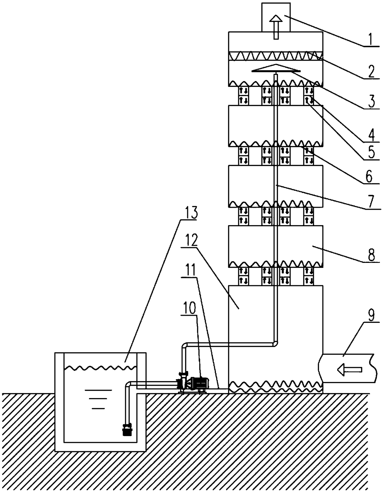
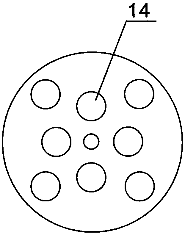
[0030] This embodiment provides a soot desulfurization device, such as Figure 1 to Figure 2 As shown, there are multiple desulfurization cylinders 8 and upper liquid pipes 7, and the number of desulfurization cylinders 8 is multiple. The adjacent desulfurization cylinders 8 are vertically connected through the desulfurization channels 5, and the desulfurization liquid liquid surface is formed on the bottom plate 6 of the desulfurization cylinders 8; The upper liquid pipe 7 is arranged through the center of the desulfurization cylinder 8 , and the liquid outlet of the upper liquid pipe 7 is located in the top desulfurization cylinder 8 .

[0031] During implementation, the water pump 10 is used to feed the desulfurization liquid into the top desulfurization cylinder 8 through the upper liquid pipe, and the desulfurization liquid flows from the top desulfurization cylinder 8 to the bottom desulfurization cylinder 8, forming a plurality of desulfurization liquids on the bottom pl...

Embodiment 2

[0047] This embodiment provides a soot desulfurization method, specifically using the soot desulfurization device in Embodiment 1 for desulfurization, including the following steps:

[0048] Step 1: Turn on the water pump, supply desulfurization liquid into the top desulfurization cylinder, the desulfurization liquid flows from the upper desulfurization cylinder to the lower desulfurization cylinder, and form multiple desulfurization liquid levels on the bottom plate 6 of multiple desulfurization cylinders 8 .

[0049] Before step 1, first fill the desulfurization liquid pool 13 with desulfurization liquid of appropriate concentration, and select appropriate power pumps and fans according to parameters such as the amount of soot to be desulfurized and the sulfur content of the soot, and complete other preparatory work before desulfurization. If the desulfurization cylinder 8 and the desulfurization passage 8 are detachable structures, select an appropriate number of desulfuriza...


PUM


Abstract

The invention relates to a smoke desulfurization device and method, belongs to the technical field of environmental protection equipment and solves the problems of poor desulfurization effect and highoperation cost due to short contact time and small contact area of smoke with a desulfurized liquid in the prior art. The smoke desulfurization device comprises a plurality of desulfurization barrelsand a liquid feeding pipe, wherein the adjacent desulfurization barrels are vertically communicated through a desulfurization channel, and a desulfurized liquid level is formed on a bottom plate of each desulfurization barrel; the liquid feeding pipe penetrates through centers of the desulfurization barrels, and a liquid outlet of the liquid feeding pipe is located in the top desulfurization barrel. By means of the desulfurization method of the smoke desulfurization device, the height of the desulfurized liquid level is can be adjusted, and the adjustability of the desulfurized liquid level is realized. The provided smoke desulfurization device and method can be widely used for smoke desulfurization in industrial production such as power generation, brick making, tile burning, incineration and the like.

Description

technical field [0001] The invention relates to the technical field of environmental protection equipment, in particular to a soot desulfurization device and method. Background technique [0002] With the development of human society, environmental problems become increasingly prominent. In the process of power generation, brick making, tile burning, incineration, etc., a large amount of smoke and dust appear, and the nitrogen oxides and sulfur oxides in the smoke and dust are important sources of air pollution. [0003] There are many desulfurization methods for flue dust on the market. Generally, various desulfurization liquids react with flue dust to produce another substance soluble in desulfurization liquid and then separate them. There are two kinds of reaction processes between smoke and desulfurization liquid. One is that the smoke and dust are directly inserted into the desulfurization tank through the pipeline, and the smoke and dust are desulfurized by this desul...

Claims


Application Information

Patent Timeline
Patent Type & Authority Applications(China)
IPC IPC(8): B01D53/78B01D53/50
CPCB01D53/50B01D53/78
Inventor 程红梅董昱霞高峰杨玉贵彭维红张志镇袁丽
Owner CHINA UNIV OF MINING & TECH
Why Eureka
Try Eureka