A visual long-distance dense phase positive pressure pneumatic conveying test device

A technology of pneumatic conveying and testing equipment, which is applied in the direction of conveying bulk materials, conveyors, transportation and packaging, etc., and can solve problems such as no automatic blockage removal function, unfavorable conveying stability control, and large flow influence

Active Publication Date: 2019-11-05
TAIYUAN UNIV OF TECH
View PDF7 Cites 0 Cited by
  • Summary
  • Abstract
  • Description
  • Claims
  • Application Information

AI Technical Summary

Problems solved by technology

At present, the technologies disclosed about the solid powder particle pneumatic conveying device, such as CN201367257Y and CN202529573U, all use gas supply pipelines or blowing aids to realize long-distance dense phase pneumatic transportation. Disturbs the operation law of solid powder particles in the pipeline, which is not conducive to stable transportation; CN105347040A is equipped with a pressure charging port, a powder inlet, and a nitrogen replacement gas pressure charging port on the top head of the discharge type delivery tank to realize high-pressure For the powder transportation of the lower ultra-high dense phase, the delivery pressure of each section of the delivery pipeline cannot be monitored in real time, and it does not have the function of automatic blockage removal, which is prone to blockage; Airflow inlets are arranged around the material opening, and the size of the airflow injection has a great influence on the flow in the tank, which is not conducive to the stable control of conveying, and the concentration of pulverized coal is relatively low; CN103213845A installs a star feeder at the bottom of the material tank to Control the material flow rate, which makes the power running parts added to the delivery tank, which seriously affects the safety of the high-pressure system; CN105858226A and CN201052926 only provide a pneumatic conveying device and method for powder and small particle materials, and do not affect the conveying flow. phase and system control etc.

Method used


Image

  • A visual long-distance dense phase positive pressure pneumatic conveying test device
  • A visual long-distance dense phase positive pressure pneumatic conveying test device

Examples


Embodiment approach 1

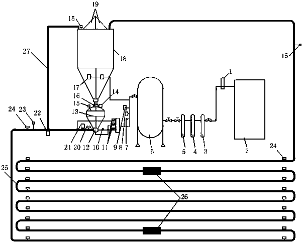
[0041] In this implementation example, the delivery pipeline has a diameter of DN100 and a length of 600 m as an example. Conduct visual long-distance dense-phase pneumatic conveying experiments.

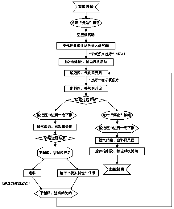
[0042] Such as figure 1 As shown, the experimental method using the described visual long-distance dense-phase positive pressure pneumatic conveying test device includes the following steps:

[0043] Step 1: Before the experiment, set the delivery pipeline 25 to a diameter of DN100 and a length of 600m; adjust one Ф8mm air intake hole and all 45 Ф3mm air intake holes of the porous orifice throttling device 10 to open up to obtain stable air Volumetric flow rate, check the running status of the air compressor and the tightness of the air storage tank and various valves.

[0044] Step 2: Start the air compressor to compress the air so that the pressure in the air storage tank reaches above 0.5MPa, and then perform an air blowing process on the experimental system without feeding.

...

Embodiment approach 2

[0049] Such as figure 1 As shown, in this implementation example, the conveying pipeline has a diameter of DN125 and a length of 800m as an example. Conduct visual long-distance dense-phase pneumatic conveying experiments.

[0050] The experimental method using the described visualized long-distance dense-phase positive pressure pneumatic conveying test device includes the following steps:

[0051] Step 1: Before the experiment, set the conveying pipeline 25 to a diameter of DN125 and a length of 800m; adjust one Ф8mm air intake hole and some 26 Ф3mm air intake holes of the porous orifice throttling device 10 to open to obtain a stable air volume Flow rate, check the running status of the air compressor and the tightness of the air storage tank and various valves.

[0052] Step 2: Start the air compressor to compress the air so that the pressure in the air storage tank reaches above 0.5MPa, and then perform an air blowing process on the experimental system without feeding. ...


PUM


Abstract

The invention discloses a visual long-distance concentrated-phase positive-pressure pneumatic conveying test device, and relates to the technical field of pneumatic conveying. The device is composed of an air source power system, a feeding-mixing-accelerating system, a pipeline conveying system, a gas-solid separation system, a measuring and monitoring system and a control system. According to thevisual long-distance concentrated-phase positive-pressure pneumatic conveying test device, a multi-parameter-adjustable concentrated-phase positive-pressure pneumatic conveying test can be achieved;visual monitoring is carried out on the flow state of solid powder particles in a conveying pipeline through a capacitive sensor, and parameters such as the solid phase holdup, the solid instantaneous flow rate, the solid accumulated volume flow and the like in the pipeline can be directly measured; concentrated-phase pneumatic conveying tests with different conveying lengths are realized; the internal pressure drop condition of the conveying pipeline can be monitored in real time through a pressure transmitter, so that the blockage situation of the pipeline is automatically distinguished, and the automatic blockage removal function is achieved; and meanwhile, concentrated-phase pneumatic conveying tests under different material-gas ratio conditions can be realized. The visual long-distance concentrated-phase positive-pressure pneumatic conveying test device is mainly used for the test research for monitoring the internal flow type and relevant parameters of the solid powder particlesin the long-distance pipeline conveying process.

Description

technical field [0001] The invention relates to the technical field of pneumatic conveying, in particular to a visual long-distance dense-phase positive pressure pneumatic conveying test device. Background technique [0002] At present, the pneumatic conveying of solid powder particles is mainly divided into dilute phase pneumatic conveying and dense phase pneumatic conveying. Pneumatic conveying technology has been rapidly developed and applied in all countries in the world. The conveying objects have rapidly developed from early flour, grain and letters to metallurgy, cement, chemical industry, mining, electric power and other fields. It is widely used in the bottom of dust collectors in coal-fired power plants in my country. Fly ash transportation, coal mine goaf filling, dry coal powder hydrogenation coal gasification and IGCC power generation and other engineering fields. Due to the low solid-gas ratio of dilute-phase pneumatic conveying, high energy consumption, and se...

Claims


Application Information

Patent Timeline
Patent Type & Authority Patents(China)
IPC IPC(8): B65G53/16B65G53/66
CPCB65G53/16B65G53/66
Inventor 张小强张东峰王开耿毅德姜玉龙
Owner TAIYUAN UNIV OF TECH
Why Eureka
Try Eureka