Method for designing safety drilling fluid density window during shale formation drilling

A technology of drilling fluid density and design method, which is applied in the direction of wellbore/well components, earthwork drilling and production, etc., to achieve the effect of authentic and reliable design of safe drilling fluid density window, increase construction cost, and avoid unreasonable design of drilling fluid density

Active Publication Date: 2018-11-20
NORTHEAST GASOLINEEUM UNIV
View PDF6 Cites 9 Cited by
  • Summary
  • Abstract
  • Description
  • Claims
  • Application Information

AI Technical Summary

Problems solved by technology

[0010] The object of the present invention is to provide a method for designing a safe drilling fluid density window for drilling in shale formations. This method for designing a safe drilling fluid density window for drilling in shale formations is used to solve the well wall rupture of the upper and lower limits of drilling fluid density in shale formation drilling. Pressure and collapse pressure calculation issues

Method used


Image

  • Method for designing safety drilling fluid density window during shale formation drilling
  • Method for designing safety drilling fluid density window during shale formation drilling
  • Method for designing safety drilling fluid density window during shale formation drilling

Examples


Embodiment Construction

[0040] The present invention is described further below:

[0041] The design method of the safe drilling fluid density window for drilling in shale formations is as follows:

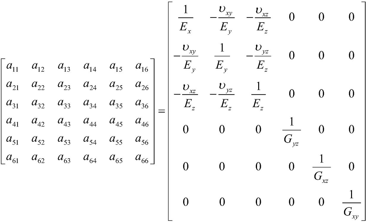
[0042] Step 1: Carry out shale rock mechanics experiments in the target interval of the target well in the drilling block to test the in-situ stress, formation pore pressure, elastic modulus of shale in different directions and Poisson's ratio.

[0043] Step 2: Select a certain well depth value for the target well target layer, and convert the borehole Cartesian coordinate system, in-situ stress coordinate system and geodetic coordinate system according to the designed wellbore structure data to prepare for borehole force analysis .

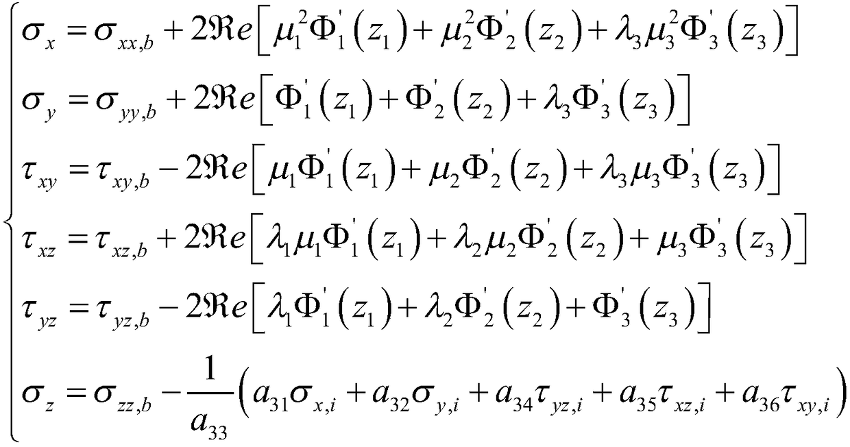
[0044] Step 3, considering the shale formation as a transversely isotropic porous medium, calculating the stress components of the borehole wall caused by the ground stress and the drilling fluid pressure in the borehole;

[0045] Among them, the stress components of the ...


PUM


Abstract

The invention relates to a method for designing a safety drilling fluid density window during shale formation drilling. The method specifically comprises the following steps: testing crustal stress, formation pore pressure and the like; transforming a borehole rectangular coordinate system, a geostress coordinate system and a geodetic coordinate system; calculating each stress component of the well walls caused by geostress and drilling fluid pressure in the borehole; transforming effective stress of each stress component on the well walls in the borehole rectangular coordinate system into aneffective stress form in a borehole polar coordinate system; deducing mechanical laws of tensile and compressive shear failure occurring in wall rock during shale drilling, namely calculating the pressure of drilling fluid in the borehole when tensile and compressive shear failure occurs at different positions of the wall along the circumferential direction of the borehole, and respectively determining the converted drilling fluid density corresponding to the fracture pressure and collapse pressure; summarizing the converted drilling fluid density corresponding to the fracture pressure and collapse pressure at all well depths on the interval of interest of a target well, and drawing the safety drilling fluid density window. According to the method disclosed by the invention, the design result of the safety drilling fluid density window is true and reliable.

Description

technical field [0001] The invention relates to a wellbore stability evaluation technology for drilling in shale formations, in particular to a method for designing a safe drilling fluid density window for drilling in shale formations. Background technique [0002] Shale gas has been regarded as an important sustainable energy alternative to coal and conventional oil and natural gas. The total global resources of shale gas are about 4.56×10 14 m 3 , accounting for about 50% of the world's unconventional oil and gas resources, equivalent to 1.4 times of conventional natural gas, has been recognized as an important energy source that changes the world's energy pattern and enables global oil and gas exploration to show good development prospects. [0003] According to statistics, there are about 600×10 natural gas supply in my country in 2015 8 m 3 The left and right gap needs to be imported, and it is estimated that by 2020, the domestic natural gas gap will reach 1000×10 ...

Claims


Application Information

Patent Timeline
Patent Type & Authority Applications(China)
IPC IPC(8): E21B49/00
CPCE21B49/005
Inventor 李玉伟刘佳张军胡超洋高睿曾博
Owner NORTHEAST GASOLINEEUM UNIV
Why Eureka
Try Eureka