Stamping retainer provided with lubricating oil duct and machining method

A technology of lubricating oil channels and cages, which is applied in the direction of bearing components, shafts and bearings, bearing cooling, etc., can solve problems such as heat generation, hindering bearing speed, and excessive sliding friction, so as to increase the area, reduce friction, and reduce The effect of frictional resistance

Active Publication Date: 2018-11-20
HANGZHOU DIANZI UNIV
View PDF9 Cites 6 Cited by
  • Summary
  • Abstract
  • Description
  • Claims
  • Application Information

AI Technical Summary

Problems solved by technology

[0004] Aiming at the problem that the sliding friction between the rolling bearing cage and the rolling body is too large, which hinders the further increase of the bearing speed and brings about serious heat generation under high-speed working conditions, the invention proposes a cage with a special structure and a bionic surface topography. The processing method transforms the surface-to-surface contact between the traditional cage and rolling elements into surface-to-line contact to reduce frictional resistance, and the rounded corner design of the several-shaped structure avoids the premature formation of subsurface cracks caused by the cutting effect of the contact surface. The normal working life of the bearing; at the same time, a texture with bionic surface topography is provided in the contact oil film area between the rolling element and the cage to improve the characteristics of the dynamic pressure oil film and improve the lubrication effect

Method used


Image

  • Stamping retainer provided with lubricating oil duct and machining method
  • Stamping retainer provided with lubricating oil duct and machining method
  • Stamping retainer provided with lubricating oil duct and machining method

Examples


Embodiment Construction

[0031] The technical solutions in the embodiments of the present invention will be clearly and completely described below in conjunction with the accompanying drawings in the embodiments of the present invention. Obviously, the described embodiments are only a part of the embodiments of the present invention, rather than all the embodiments. Based on the embodiments of the present invention, all other embodiments obtained by those of ordinary skill in the art without creative work shall fall within the protection scope of the present invention.

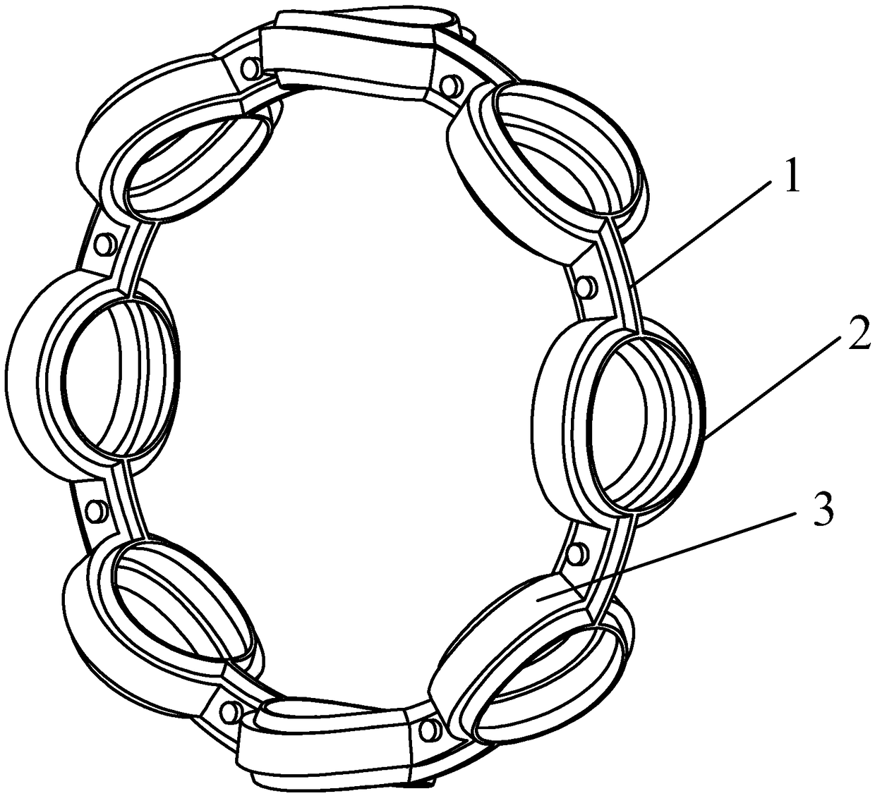
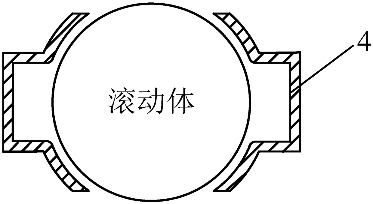
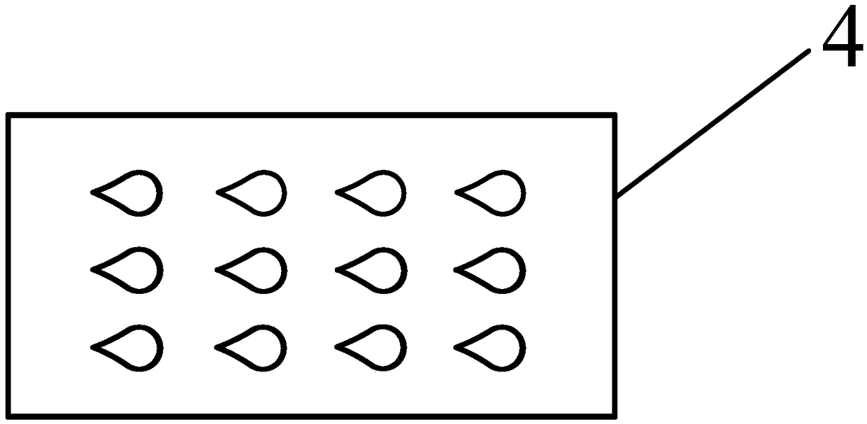
[0032] reference figure 1 with figure 2 , A stamped cage with lubricating oil channel, comprising two cage single-sided frame bodies 1 riveted together, and the two cage single-sided frame bodies 1 enclose a plurality of pockets for accommodating rolling elements distributed in the circumferential direction Hole 2; the side wall of the pocket 2 is provided with an annular annular groove 3, the bottom 4 of the annular groove, the side wal...


PUM


Abstract

The invention discloses a stamping retainer provided with a lubricating oil duct and a machining method. The sliding friction between an existing rolling bearing retainer and a rolling body is too large. An annular groove is formed in the side wall of each pocket of the stamping retainer in the circumferential direction of the pocket, and rounded corners are chamfered between the two side walls ofeach annular groove and the side wall of the corresponding pocket. Microstructures are arranged at the bottoms of the annular grooves. The machining method of the stamping retainer comprises the following steps of material checking; primary machining of the retainer to form a steel ring and finishing treatment; formation of the microstructures; stamping formation of a retainer body on one side ofthe retainer; surface treatment; and riveting. According to the stamping retainer provided with the lubricating oil duct and the machining method, surface-to-surface contact between a traditional retainer and a rolling body is converted into surface-to-line contact, so that the frictional resistance is reduced; through the design of the rounded corners of an n-shaped structure, the situation thatsecondary surface cracks are formed too early due to cutting of the contact surface is avoided, and the normal service life of a bearing is ensured; and meanwhile, the structures with bionic surfacetopography are arranged on oil film contact areas of a rolling body and the retainer, so that the dynamic pressure oil film properties are improved, and the lubricating effect is improved.

Description

Technical field [0001] The invention belongs to the technical field of rolling bearings, and specifically relates to a stamping cage with a special structure and a processing method based on anti-wear, bionics. Background technique [0002] High-reliability and high-precision high-speed bearing research and development capabilities have become a bottleneck restricting the improvement of my country's high-end equipment manufacturing industry. With the improvement of my country's industrial level, high-speed bearings are widely used in aerospace, precision machine tools, high-speed electric spindles, rail transit, ultra-precision medical machinery and other fields. In high-speed bearings, although graphite bearings, SiC bearings, Si3N4 bearings and other new material bearings show better high-speed characteristics in recent years, steel-based bearings still occupy an absolute dominant position in the industrial field. For open-type oil-lubricated rolling bearings, the sliding fric...

Claims


Application Information

Patent Timeline
IPC IPC(8): F16C33/38F16C33/66F16C37/00
CPCF16C33/38F16C33/6603F16C37/00
Inventor 吴参熊锐峰李兴林倪敬
Owner HANGZHOU DIANZI UNIV
Why Eureka
Try Eureka