
Soldering iron calibration method

A calibration method and soldering iron technology, applied in the field of calibration, can solve the problems of high requirements for calibration personnel, long time-consuming, increased gaps, etc., to achieve the effect of ensuring measurement accuracy and efficiency, welding yield, and consistency

Active Publication Date: 2018-11-20
WEIFANG LOKOMO PRECISION IND
View PDF6 Cites 0 Cited by
  • Summary
  • Abstract
  • Description
  • Claims
  • Application Information

AI Technical Summary

Problems solved by technology

During the long-term use of the soldering iron tip, the gap between the soldering iron tip and the pad will continue to increase due to wear and corrosion.
In addition, because the height consistency of the soldering iron tip itself is not good, after replacing the soldering iron tip, the gap between the new soldering iron tip and the pad will also change
If it is adjusted manually, it will take a long time, and the requirements for the calibration personnel are high

Method used


Image

  • Soldering iron calibration method
  • Soldering iron calibration method

Examples


Embodiment Construction

[0026] In order to make the object, technical solution and advantages of the present invention clearer, the present invention will be further described in detail below in conjunction with the accompanying drawings and embodiments. It should be understood that the specific embodiments described here are only used to explain the present invention, not to limit the present invention.

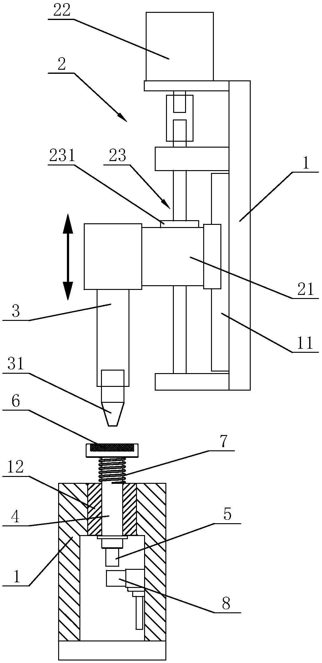
[0027] A soldering iron calibration method based on a soldering iron calibration structure such as figure 1 and figure 2 Commonly shown, a soldering iron calibration structure includes a bracket 1, a soldering iron 3 driven by a linear servo mechanism 2 is installed on the bracket 1, and a soldering iron tip 31 is installed on the soldering iron 3. In this embodiment, the linear servo mechanism 2 includes a sliding seat 21 and a screw nut mechanism 23 driven by a servo motor 22. The guide rail 11 is fixedly installed on the bracket 1, and the sliding seat 21 is slidably installed on the guide rai...


PUM


Abstract

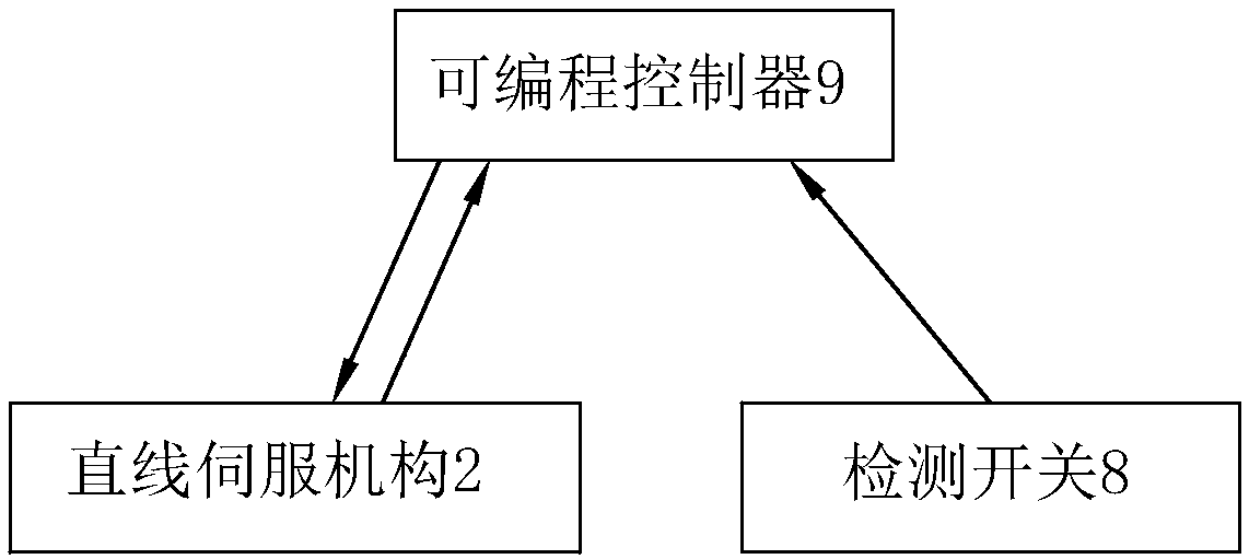
The invention discloses a soldering iron calibration method, belongs to the calibration technology field and is based on the soldering iron calibration structure. The soldering iron calibration structure comprises a support, a detection switch, a soldering iron driven by a linear servo mechanism and a soldering iron tip mounted on the soldering iron, wherein the support is equipped with a guide shaft in a sliding mode, one end of the guide shaft is provided with an insulation element, the other end is provided with a detection piece, the detection switch is electrically connected with an electrical control unit, the electrical control unit is electrically connected with the linear servo mechanism, the soldering iron tip is driven by the linear servo mechanism to move and contact the insulation element, the detection piece is further driven to move, when a signal is detected by the detection switch, position data of the linear servo mechanism is read by the electrical control unit, position data of a linear servo mechanism of a standard soldering iron tip is compared with the position data of the linear servo mechanism of the detected soldering iron tip, and difference is the compensation amount. The soldering iron calibration structure is advantaged in that welding defects caused by wear, corrosion and replacement of the soldering iron tip can be reduced, and stability, consistency and the utilization rate of the device are improved.

Description

technical field [0001] The invention belongs to the technical field of calibration, and in particular relates to a method for calibrating a soldering iron. Background technique [0002] In the production of electronic products, the joints of components need to be soldered. For example: in the assembly process of LCM (LCD Module, liquid crystal display module), the backlight pins of BL (Back Light, backlight board) and the pads of FPC (Flexible Printed Circuit, flexible circuit board) need to be connected by soldering. A soldering iron is the most commonly used soldering tool. [0003] In the process of automatic welding production, due to the needs of the process, it is required to ensure that the gap between the soldering iron tip of the soldering iron and the pad is within a certain range, otherwise poor welding will easily occur. However, during the long-term use of the soldering iron tip, the gap between the soldering iron tip and the pad will continue to increase due ...

Claims


Application Information

Patent Timeline
Patent Type & Authority Applications(China)
IPC IPC(8): G01B5/06G01B5/00
CPCG01B5/00G01B5/061
Inventor 张睿鱼志文董旭日
Owner WEIFANG LOKOMO PRECISION IND
Learn More