Method for detecting soil and root system structure based on CT scanning of liftable clamp

A technology of CT scanning and root system, which is applied in the field of agricultural engineering, can solve the problems of inapplicable plant root system sample whole and partial detection separately, and the height of the clamp cannot be adjusted, etc., and achieves the effect of strong applicability and simple operation

Pending Publication Date: 2018-11-20
SOUTHWEST UNIV
View PDF0 Cites 5 Cited by
  • Summary
  • Abstract
  • Description
  • Claims
  • Application Information

AI Technical Summary

Problems solved by technology

[0006] In view of this, in order to solve the problem that the height of the sample fixture used in the existing root CT scan detection technology cannot be adjusted and is not suitable for the overall and local detection of plant root samples, the present invention provides a CT scan detection soil based on a liftable clamp. and root structure method

Method used


Image

  • Method for detecting soil and root system structure based on CT scanning of liftable clamp
  • Method for detecting soil and root system structure based on CT scanning of liftable clamp
  • Method for detecting soil and root system structure based on CT scanning of liftable clamp

Examples


Embodiment 1

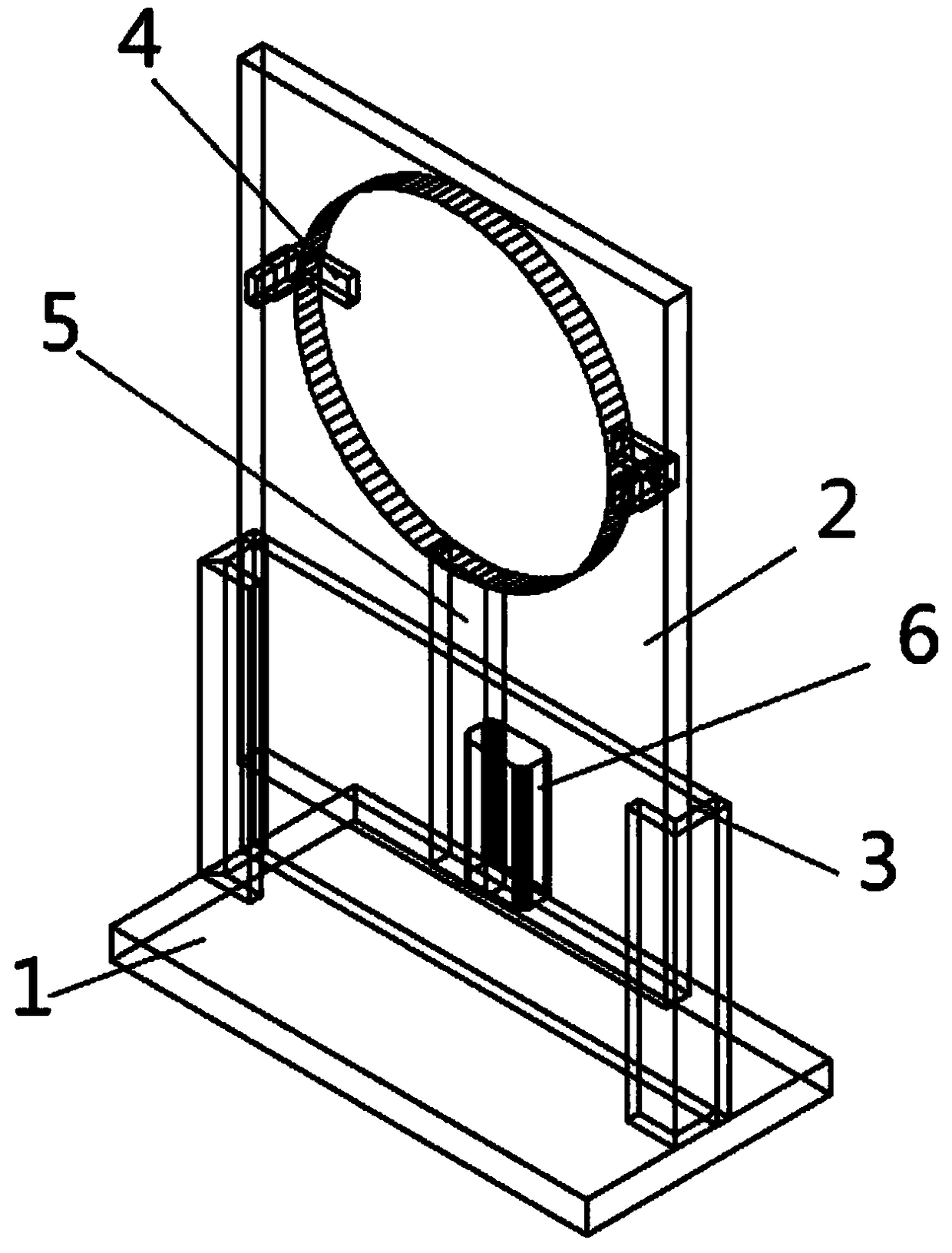
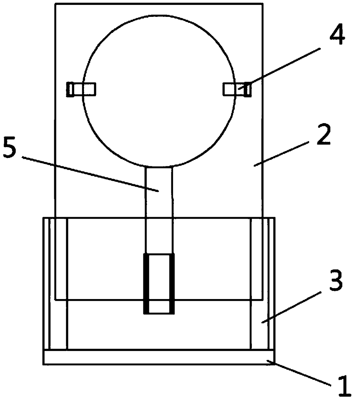
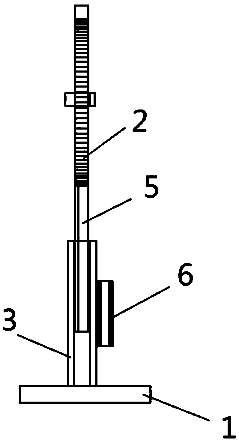
[0045] like Figure 1~4 The shown CT scan detects the overall structure of the plant root system, which mainly includes a plug-in base 1 and a liftable bracket 2;

[0046] The base 1 includes a bottom plate and a lifting groove 3 fixedly installed on the bottom plate with "C"-shaped or "U"-shaped chute on both sides. The bottom plate and the lifting groove 3 are integrally formed. The second function is to lower the center of gravity of the entire device, so that the clamp does not fall due to the unstable center of gravity during the rotation of the worktable, and the bracket 2 can move up and down along the lifting groove 3;

[0047] The bracket 2 is provided with a magnetic strip slot, and the number of the magnetic strip slot is 1. The magnetic strip slot is set at the lower part of the bracket 2 in the middle position. A magnetic strip 5 is clamped in the magnetic strip slot, and the slot wall of the lifting slot 3 can be detachably installed. For the magnet 6 used in co...

Embodiment 2

[0054] like Figure 5-8 The shown CT scan detects the local structure of the plant root system. The difference between Example 2 and Example 1 is that the bracket 2 is in the shape of a plate, and the width of the bracket 2 is the same as the distance between the inner walls of the two sides of the lifting groove 3. Set in the lift groove 3 , a semicircular clip slot 7 is opened in the middle of the upper end of the bracket 2 .

[0055] A method for detecting a local structure of a plant root system based on CT scanning of a liftable fixture, comprising the following steps:

[0056] A. Sample collection: The samples to be tested are collected with special tools respectively. The plant root chip sample is prepared by placing the preserved dry seeds on a filter paper bed, adding clean water and incubating in a 37°C incubator for 48 hours, and taking the active plants. The seeds were placed in the center of the chip, and the seeds were fixed with agar to keep the seeds moist. Ev...

Embodiment 3

[0061] like Figures 9 to 12 The CT scanning detection soil structure fixture shown, the difference between Embodiment 3 and Embodiment 1 is that the bracket 2 is two support rods clamped in the lifting groove 3, the number of the magnetic strip grooves is 2, and the magnetic strip grooves are 2. They are respectively set in the middle position of the lower part of the support rod. Two object storage platforms 8 are fixedly installed above the support rod. The groove and the curved bottom can fix the soil test tube to be tested on the bracket 2 . The storage table 8 and the bracket 2 are integrally formed. The length of the magnet 6 is 2cm, and the four corners of the magnet 6 are arc-shaped.

[0062] A method for detecting soil structure based on CT scanning of a liftable fixture, comprising the following steps:

[0063] A. Sample collection: The samples to be tested are collected with special tools respectively. The soil samples are collected by using a transparent plexigla...


PUM


Abstract

The invention belongs to the technical field of agricultural engineering, and relates to a method for detecting a soil and root system structure based on CT scanning of a liftable clamp. The method comprises the steps of sample cultivation, sample fixation, CT scanning and data processing, wherein in the step of sample fixation, a sample to be detected is fixedly mounted on a support, the supportis clamped in a lifting groove in a base plate in a relatively sliding manner, a magnetic stripe is placed in a magnetic stripe groove in the support, the support is fixed at an appropriate height inside the lifting groove through the magnetic stripe and a magnet placed on the outer wall of the lifting groove, and the sample to be detected is a plant root chip or a test tube with a soil column; inthe step of CT scanning, a lifting device for fixing the sample to be detected is placed on a working table of a CT scanner for scanning detection. The problems that the height of a sample clamped used in the conventional root system CT scanning detection technology cannot be adjusted and the sample clamp is not suitable for overall detection and local detection for the plant root system sample respectively are solved.

Description

technical field [0001] The invention belongs to the technical field of agricultural engineering, and relates to a method for detecting soil and root system structure by CT scanning based on liftable clamps, in particular to a liftable magnetic sample clamp which is suitable for three-dimensional micro-nano CT scan detection of soil and plant root systems microstructural approach. Background technique [0002] The pedosphere composed of soil is an important place for material circulation and energy conversion in the natural environment, and it is one of the most active and vital circles in the ecological environment. Due to environmental changes, population growth and ecological destruction, soil problems are becoming more and more serious. In recent years, the country's scientific research priorities in agriculture and the environment have all mentioned issues such as land structure, soil erosion, and soil pollution. As a large agricultural country in my country, soil qual...

Claims


Application Information

Patent Timeline
Patent Type & Authority Applications(China)
IPC IPC(8): G01N23/046
CPCG01N23/046G01N2223/309G01N2223/419G01N2223/616
Inventor 陈凤柴慧慧余玲
Owner SOUTHWEST UNIV
Why Eureka
Try Eureka