
High-altitude falling intelligent rescue system

An intelligent, hardware system technology, applied in the field of high-altitude fall intelligent rescue system, can solve the problems of slow lateral displacement, unreasonable motor connection, and easy to be blocked by buildings

Active Publication Date: 2018-11-23
UNIV OF SHANGHAI FOR SCI & TECH
View PDF4 Cites 5 Cited by
  • Summary
  • Abstract
  • Description
  • Claims
  • Application Information

AI Technical Summary

Problems solved by technology

[0003] This commonly used fire rescue equipment, the binocular vision system is located on the car, the elevation angle is very large, it is easily blocked by buildings, and it is easily interfered by factors such as weather and light, so that the target cannot be recognized; the target is easily affected by wind or collision obstacles during the fall process. The trajectory is changed due to the influence of objects, and the method of locating the target and then calculating the landing point has a large error; using a traditional air cushion as a buffer device, without taking measures to prevent the target from popping up, will cause secondary damage; it can only locate and track a single target. Unable to deal with fire and other situations where there may be multiple targets needing rescue; using Mecanum wheels as a means of displacement, the lateral displacement speed is too slow and not practical; it is unreasonable to connect the motor directly to the wheels without changing the transmission ratio, and it is easy to be damaged Motor: using the traditional coil spring suspension, the elasticity is small and the buffering effect cannot be achieved, and the target will be ejected when the elasticity is large, causing secondary damage

Method used


Image

  • High-altitude falling intelligent rescue system
  • High-altitude falling intelligent rescue system
  • High-altitude falling intelligent rescue system

Examples


Embodiment Construction

[0026] The following describes several preferred embodiments of the present invention with reference to the accompanying drawings, so as to make the technical content clearer and easier to understand. The present invention can be embodied in many different forms of embodiments, and the protection scope of the present invention is not limited to the embodiments mentioned herein.

[0027] In the drawings, components with the same structure are denoted by the same numerals, and components with similar structures or functions are denoted by similar numerals. The size and thickness of each component shown in the drawings are arbitrarily shown, and the present invention does not limit the size and thickness of each component. In order to make the illustration clearer, the thickness of parts is exaggerated appropriately in some places in the drawings.

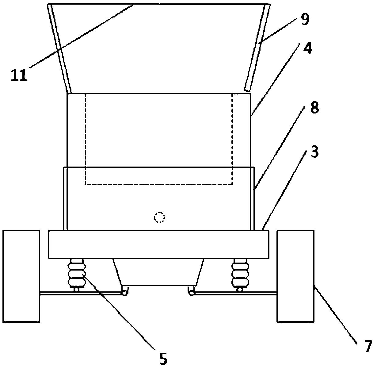
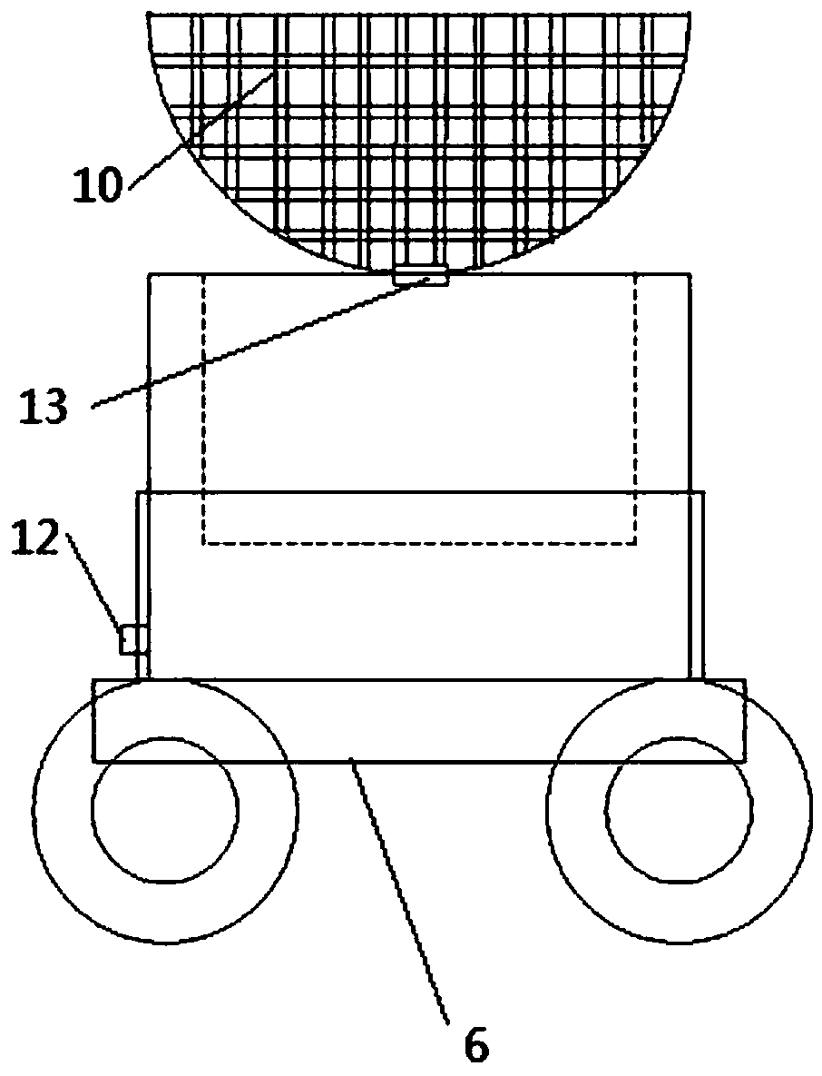
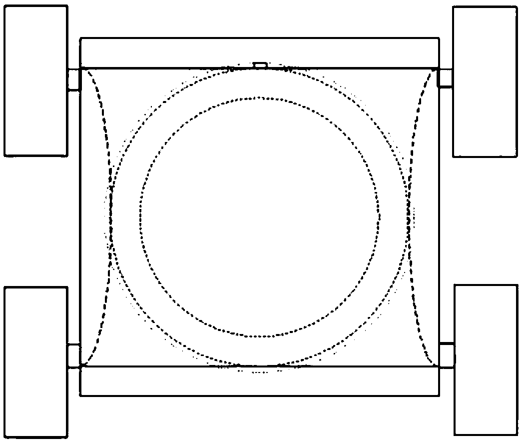
[0028] High-altitude falling intelligent rescue system, the hardware system includes the air part and the ground part. Such as F...


PUM


Abstract

The invention discloses a high-altitude falling intelligent rescue system, and relates to the field of fire rescue. The system comprises a software system and a hardware system, wherein the software system comprises an SLAM module, a machine vision target tracking module, a control module and a communication module, the hardware system comprises an air part and a ground part, the air part comprises an unmanned aerial vehicle and a machine vision system, the machine vision system is fixedly arranged under the unmanned aerial vehicle, the ground part comprises an unmanned vehicle, a buffer column-shaped air cushion, bag-type multi-curve air spring suspension systems, an air pump and a power supply, wherein the unmanned vehicle comprises a chassis, wheels and a fence, hub motors are arrangedin the wheels, the wheels are arranged under the chassis through the bag-type multi-curve air spring suspension systems, the fence is arranged above the chassis, the buffer column-shaped air cushion is fixed through the fence, and two split-structure covers are arranged above the buffer column-shaped air cushion. The system has the advantages of being high in real-time performance, high in environmental adaptability, high in rescue height, capable of preventing secondary injury and high in response speed.

Description

technical field [0001] The invention relates to the field of fire rescue, in particular to an intelligent rescue system for falling from a height. Background technique [0002] With the increasing number of high-rise buildings and the height of high-rise buildings, the number of emergencies caused by the environmental conditions of high-rise buildings is also increasing. Therefore, higher requirements are put forward for high-altitude lifesaving, and efficient and practical High-altitude fire-fighting and rescue equipment, providing ground rescue for people in distress in high-rise buildings or people who jumped from the building. At present, the commonly used fire rescue equipment is to place the air cushion on the car, use the binocular vision system to identify the falling target and calculate the falling point, the car moves to this position, and the air cushion catches the target. [0003] This commonly used fire rescue equipment, the binocular vision system is located...

Claims


Application Information

Patent Timeline
Patent Type & Authority Applications(China)
IPC IPC(8): A62B1/22
CPCA62B1/22
Inventor 樊笛马素萍巨志勇张泽晨王告
Owner UNIV OF SHANGHAI FOR SCI & TECH
Learn More