
High wear-resisting oil pressure jacking rod machining process

A processing technology and technology of hydraulic ejector, which is applied in the field of processing technology of high wear-resistant hydraulic ejector pins, can solve the problems of difficulty in vertical precision control of the mounting surface, damage to molds and equipment, and high processing costs, and achieve good comprehensive mechanical properties , The difficulty of precision control is small, and the effect of reducing the friction coefficient

Active Publication Date: 2018-11-23
KUNSHAN MINAMAX PRECISION IND
View PDF5 Cites 4 Cited by
  • Summary
  • Abstract
  • Description
  • Claims
  • Application Information

AI Technical Summary

Problems solved by technology

[0004] Disadvantages of this processing technology: ①. After the overall hardening of SKH51 material, the internal and surface hardness of the material reaches HRC60±2, which is hard on the outside and brittle on the inside, and the processing cost is high. Although the wear resistance is excellent, it may Breakage due to frequent punching, resulting in damage to the mold and equipment; ②. After the ejector pin is fixed horizontally, the side of the grinding wheel is finely trimmed on the mold mounting surface, which may be due to clamping errors and friction vibration during side repair, resulting in the relative top of the mold mounting surface When the rod axis is tilted, it is difficult to control the vertical precision of the mounting surface

Method used


Image

  • High wear-resisting oil pressure jacking rod machining process
  • High wear-resisting oil pressure jacking rod machining process
  • High wear-resisting oil pressure jacking rod machining process

Examples


Embodiment Construction

[0037] The present invention will be further described below in conjunction with the accompanying drawings.

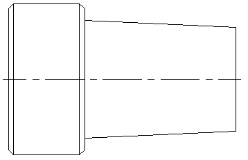
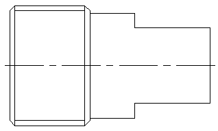
[0038] Such as Figure 1-Figure 5 As shown, a high wear-resistant hydraulic ejector processing technology includes the following steps: (1) Material preparation: select raw materials that meet the hardness requirements. The raw materials selected in this example are SKD61 raw materials, because of their excellent The performance can ensure the hardness and wear resistance of the final hydraulic ejector pin; (2) Drilling center hole: Drill a central inner hole along the length of the raw material; (3) Rough car shape: take the center hole as the axis, The shape of the green material is initially turned into shape, and an auxiliary internal thread is turned on one end of the green material, such as figure 1 As shown, heat treatment is carried out on the raw material after the auxiliary internal thread is processed to ensure that the product obtains the required structur...


PUM

PropertyMeasurementUnit
hardnessaaaaaaaaaa
hardnessaaaaaaaaaa
diameteraaaaaaaaaa

Abstract

The invention discloses a high wear-resisting oil pressure jacking rod machining process. The high wear-resisting oil pressure jacking rod machining process comprises the following steps of SKD61 rawmaterial preparing, center oil hole drilling, outline and auxiliary thread CNC rough lathing, heat treating, jacking center jig tightening and equipping, outer circle rough grinding, seal ring grooveCNC finish lathing, nitrocarburizing, outer circle and end surface finish grinding, jacking center jig dismantling and flat grinding to control the total length, inner hole CNC finish lathing (to remove the auxiliary thread), outer circle polishing and ultrafine MAX coating. According to the high wear-resisting oil pressure jacking rod machining process, SKD61 raw materials are selected and used as base materials to perform machining, by means of 'overall hard quenching and nitrocarburizing' treatment, a jacking rod is made to have the characteristics of outer hardness and inner toughness to achieve the requirements for jacking rod wear resistance and impact resistance, and by means of configuration of jacking center auxiliary datum, a jacking rod outer circle and a mold installation surface are machined in place in a same work procedure, so that the fact that the materials can also meet the jacking rod machining precision requirements even if large deformation is generated after heattreatment is guaranteed.

Description

technical field [0001] The invention relates to a processing technology of a high wear-resistant hydraulic ejector rod, belonging to the technical field of precision workpiece processing technology. Background technique [0002] As an important part of the hydraulic mold clamping mechanism, the hydraulic ejector rod mainly plays the role of force transmission in the axial mold opening and closing movement of the capping machine mold; the single mold cavity is independently controlled, and the upper mold (punch mold) of the mold Installed at one end of the hydraulic ejector pin, the assembly is evenly arranged in a circular shape in the compression molding mechanism according to the number of cavities, and the precision of the ejector pin directly affects the accuracy of mold clamping. [0003] The hydraulic ejector pin is traditionally made of SKH51 material through the process of "raw raw material roughening → overall hardening → finishing" to ensure the hardness. The eject...

Claims


Application Information

Patent Timeline
Patent Type & Authority Applications(China)
IPC IPC(8): B23P15/00
CPCB23P15/00
Inventor 杨杰李芳
Owner KUNSHAN MINAMAX PRECISION IND
Learn More