
Aviation structural part automatic avoiding clamp device

An aviation structural parts, automatic avoidance technology, applied in the direction of clamping device, positioning device, clamping, etc., can solve the problems of reducing processing efficiency, reducing workpiece processing accuracy, increasing processing auxiliary time, etc., to improve processing efficiency and meet processing requirements Requirements, effects of improving contact methods

Inactive Publication Date: 2018-11-23
四川铭利达科技有限公司
View PDF0 Cites 11 Cited by
  • Summary
  • Abstract
  • Description
  • Claims
  • Application Information

AI Technical Summary

Problems solved by technology

Therefore, when the position of the positioning, supporting, and clamping components coincides with the cutting surface of the workpiece, the tool is likely to conflict and interfere with the positioning or clamping device, resulting in the need to stop and change the position of the clamping point during the machining process. The program controls the machining path to bypass the areas where conflicts and interferences occur. After the current step is completed, the clamping position is changed, and the unprocessed parts of the interference and conflicts are processed.
In addition to adding a lot of processing auxiliary time and reducing processing efficiency, repeated changing and clamping, the positioning error caused by the position movement of the workpiece caused by repeated clamping also reduces the machining accuracy of the workpiece.
[0004] Aiming at the error caused by clamping factors in the processing of aviation parts and the problem of repeated clamping of processed parts, an automatic avoidance fixture device for aviation structural parts is hereby invented

Method used


Image

  • Aviation structural part automatic avoiding clamp device
  • Aviation structural part automatic avoiding clamp device
  • Aviation structural part automatic avoiding clamp device

Examples


Embodiment 1

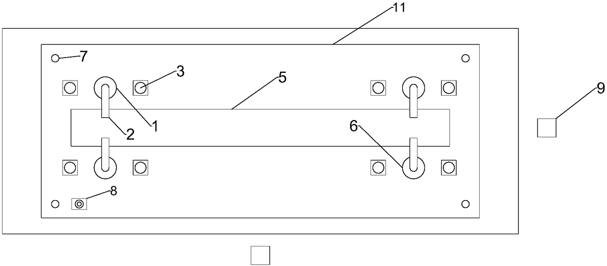
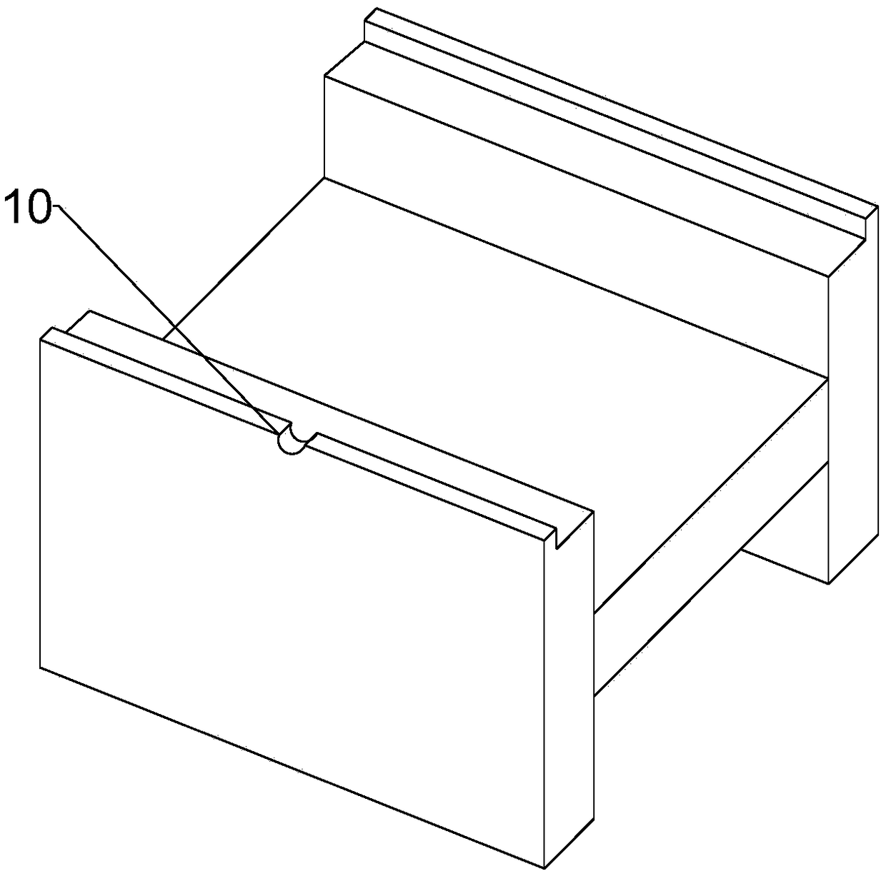
[0020] Taking the processing of an aviation aluminum alloy part as an example, an automatic avoidance fixture device for aviation structural parts includes a base plate, a clamping unit, a detection unit, a support unit, and a tool setting element. There are threaded holes at the four corners of the base plate. Eyebolts are provided on the holes. The clamping unit includes: 4 rotary clamping cylinders, and a pneumatic clamping arm is arranged on the rotary clamping cylinders. Each of the rotary clamping cylinders is divided into a group of 2 rotary clamping cylinders, which are divided into a first rotary clamping cylinder group and a second rotary clamping cylinder group, and the first rotary clamping cylinder group and the second rotary clamping cylinder group are respectively fixed At both ends of the bottom plate, the support unit includes: 3 support plates, the first support plate is set in the middle of the first rotary clamping cylinder group, and the second support pla...


PUM


Abstract

The invention discloses an aviation structural part automatic avoiding clamp device. The device comprises a bottom plate, a clamping unit, a detection unit, a supporting unit and a tool setting element. The clamping unit comprises four rotary clamping air cylinders, every two rotary clamping air cylinders form a group, and the rotary clamping air cylinders are divided into a first rotary clampingair cylinder group and a second rotary clamping air cylinder group. The supporting unit comprises at least three supporting plates which are arranged on the bottom plate, and a straight line is evenlydistributed under a clamped part. By means of multi-point clamping, the contact mode of a clamp and the part is improved, and machining errors caused by most of the clamping factors are effectively eliminated. A sensor is used for accurate positioning and pneumatic element control, so that a machining tool is automatically avoided, and machining efficiency and the machining errors caused by repeated clamping are greatly improved. According to the device, machining requirements of the whole structural part of an aircraft can be efficiently met at high quality, and the operation is convenient and fast.

Description

technical field [0001] The invention relates to the field of processing large-scale aviation parts, in particular to an automatic avoidance fixture device for aviation structural parts. Background technique [0002] With the rapid development of the aviation manufacturing industry, the performance requirements of modern aircraft are also constantly improving. In the manufacture of aviation products, large integral structural parts are widely used to replace the composite structural parts connected by riveting and bolting in the past. Compared with general mechanical parts, the processing difficulty and strength of the overall components of the aircraft are greater. Not only is the entity combination complex, the shape and position accuracy is very high, but also the thin-walled position has low stiffness and high removal rate, and the CNC machining process is very easy to produce deformation. Therefore, the manufacturing technology of large-scale aviation integral structura...

Claims


Application Information

Patent Timeline
IPC IPC(8): B23Q3/08B23Q17/00
CPCB23Q3/08B23Q3/062B23Q17/00B23Q2703/04B23Q2703/10
Inventor 佘本龙
Owner 四川铭利达科技有限公司
Learn More