Plastic shell polishing device for electronic product production

A technology for plastic casings and electronic products, applied in the direction of grinding drive devices, grinding/polishing equipment, surface polishing machine tools, etc., can solve the problems of reducing corporate profits, uneven polishing, affecting product quality, etc., and achieve improved operation stability performance, and the effect of improving controllability

Inactive Publication Date: 2018-11-23
ZHENGZHOU TIANSHUN ELECTRONICS TECH CO LTD
View PDF5 Cites 4 Cited by
  • Summary
  • Abstract
  • Description
  • Claims
  • Application Information

AI Technical Summary

Problems solved by technology

[0003] The assembly and sales of computers will involve the transportation of computers. The core part of computers is the mainframe. More advanced computers include biological computers, photonic computers, quantum computers, etc. The replacement of computers is also getting faster and faster. The computer industry is developing rapidly. During the production process of the computer, the computer case needs to be polished and polished, and the uneven polishing force will appear during the polishing and polishing process, resulting in uneven polishing, which greatly affects the quality of the product, reduces work efficiency, and reduces corporate profits.

Method used


Image

  • Plastic shell polishing device for electronic product production
  • Plastic shell polishing device for electronic product production
  • Plastic shell polishing device for electronic product production

Examples


Embodiment Construction

[0021] The following will clearly and completely describe the technical solutions in the embodiments of the present invention with reference to the accompanying drawings in the embodiments of the present invention. Obviously, the described embodiments are only some, not all, embodiments of the present invention.

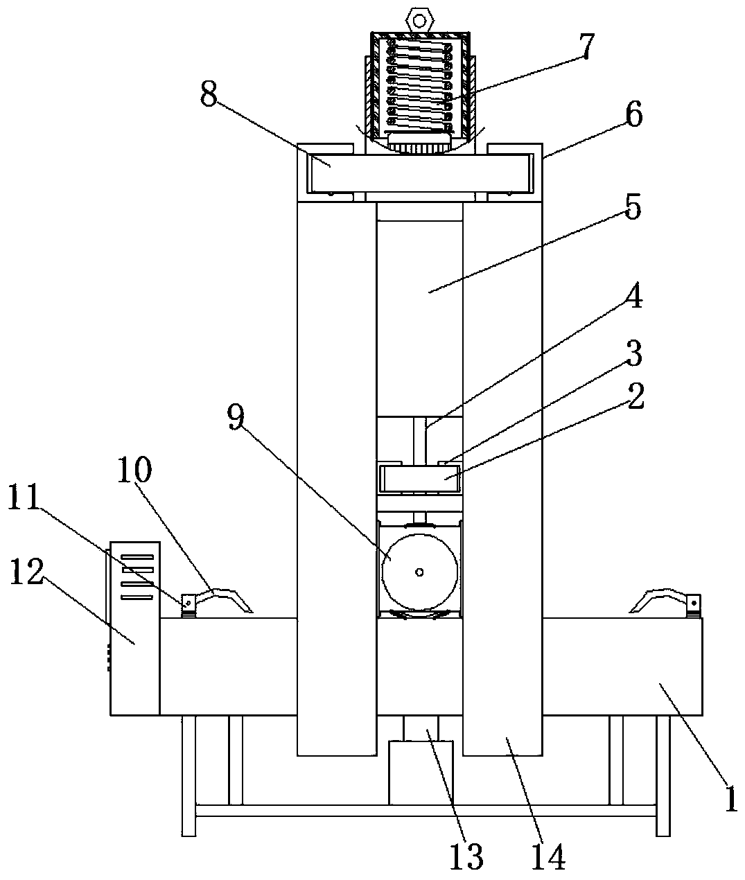
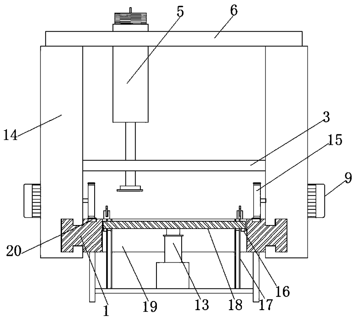
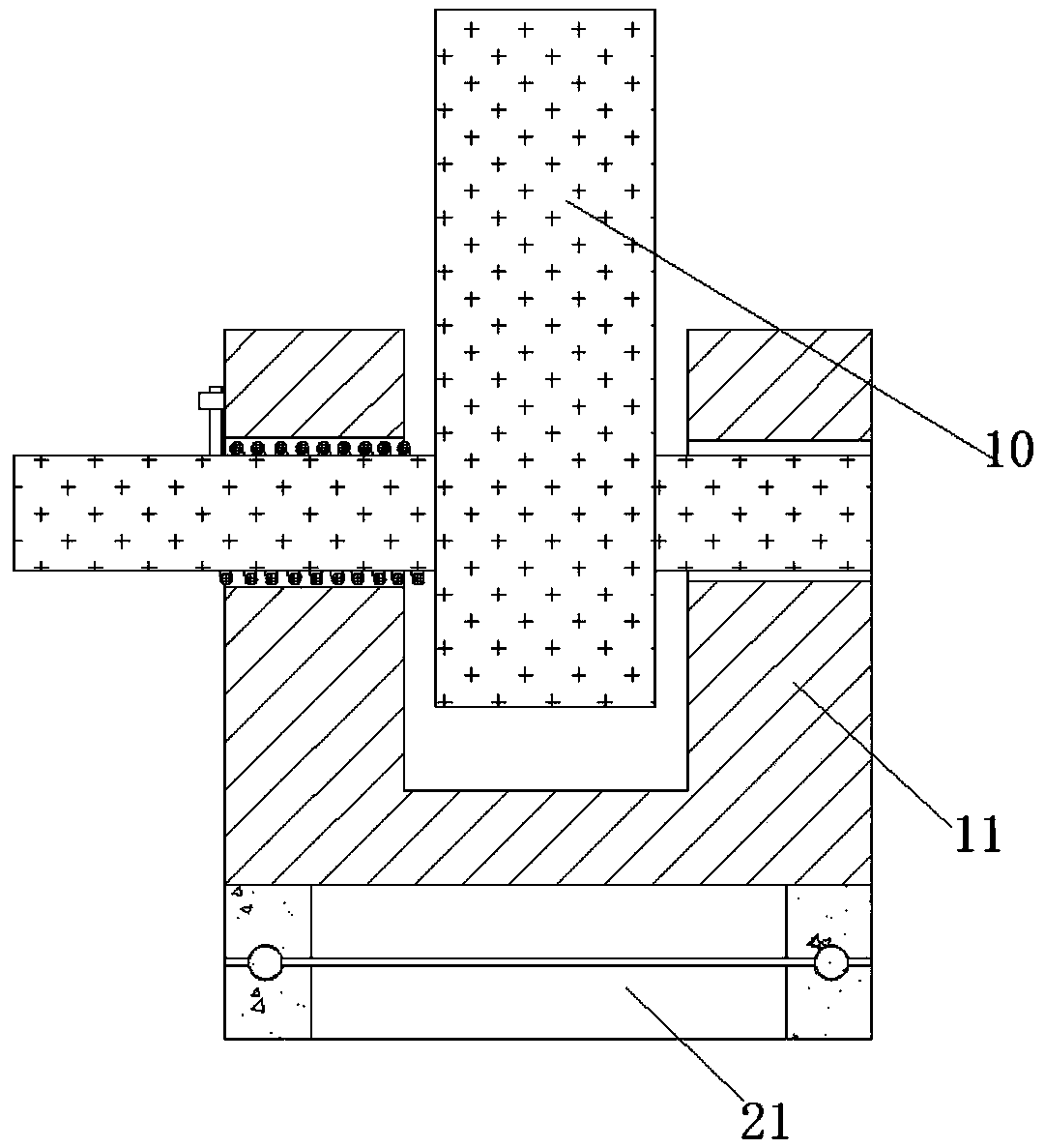
[0022] refer to Figure 1-3 , a plastic shell polishing device for electronic product production, including a workbench 1 and a support frame, rectangular grooves are opened on the upper and lower surfaces of the opposite sides of the workbench 1, and the rectangular grooves on both sides of the workbench 1 slide A slide frame 14 is connected, and two first channel steel slide rails 3 and a second channel steel slide rail 6 parallel to each other and opposite to each other are arranged between the middle and the top of the two slide frames 14, and the two second channel steel slide rails A fixed slider 8 is slidably connected between the steel slide rails 6, and a mo...


PUM


Abstract

The invention discloses a plastic shell polishing device for electronic product production. The plastic shell polishing device comprises a workbench and a supporting frame, rectangular grooves are formed in the upper surfaces and the lower surfaces of the two sides of the workbench, wherein two sides are in opposite directions, the sliding frames are connected in the rectangular grooves in the twosides of the workbench in a sliding mode, two first channel steel sliding rails and two second channel steel sliding rails are arranged between the middle and the top of the two sliding frames correspondingly, wherein the two first channel steel sliding rails and two second channel steel sliding rails are parallel to each other and the openings of the two first channel steel sliding rails and theopening of the two second channel steel sliding rails are opposite to each other, a fixed sliding block is connected between the two second channel steel sliding rails in a sliding mode, a motor boxis connected to the middle of the fixed sliding block in a clamped mode, moreover, a grinding motor is connected in the motor box in a sliding mode, the top end of an output shaft of the grinding motor is fixedly provided with a transmission rod through a coupling, and the lower end of the transmission rod is in threaded connection with a grinding disc. According to the plastic shell polishing device, different lifting heights can be selected according to different thicknesses of to-be-polished plastic shells and grinding precision, so that the pressure between the grinding disc and the plastic shells are different, the grinding effect is also different, and the controllability of the device is improved.

Description

technical field [0001] The invention relates to the technical field of electronic products, in particular to a plastic casing polishing device for electronic product production. Background technique [0002] A computer, commonly known as a computer, is an electronic computing machine used for high-speed calculations. It can perform numerical calculations, logic calculations, and storage and memory functions. It is a modern intelligent electronic device that can run according to programs and process massive amounts of data automatically and at high speed. , is composed of hardware system and software system. Computers without any software installed are called bare metal, which can be divided into five categories: supercomputers, industrial control computers, network computers, personal computers, and embedded computers. More advanced computers include biological computers, Photonic computers, quantum computers, etc. [0003] The assembly and sales of computers will involve t...

Claims


Application Information

Patent Timeline
Patent Type & Authority Applications(China)
IPC IPC(8): B24B29/02B24B19/22B24B41/02B24B47/04B24B41/06B24B47/22
CPCB24B19/22B24B29/02B24B41/02B24B41/06B24B47/04B24B47/22
Inventor 李欣
Owner ZHENGZHOU TIANSHUN ELECTRONICS TECH CO LTD
Why Eureka
Try Eureka