A biomass rolling dehydration device

A dehydration device and biomass technology, applied in the direction of presses, material forming presses, manufacturing tools, etc., can solve problems such as waste of heat energy, and achieve good cleaning effects

Active Publication Date: 2020-09-18
绍兴卿荣针纺有限公司
View PDF5 Cites 0 Cited by
  • Summary
  • Abstract
  • Description
  • Claims
  • Application Information

AI Technical Summary

Problems solved by technology

However, the moisture content in biomass is high, and direct drying will waste a lot of heat energy, so it is necessary to dehydrate the biomass in advance.

Method used


Image

  • A biomass rolling dehydration device
  • A biomass rolling dehydration device
  • A biomass rolling dehydration device

Examples


Embodiment 1

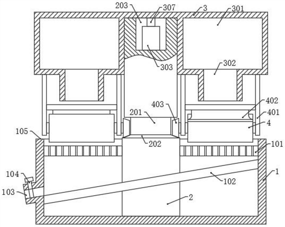
[0027] Please refer to the accompanying drawings, the present invention provides a technical solution: a biomass rolling dehydration device, including a bottom box 1, a support column 2, a rotating box 3 and a first rolling roller 4, and the bottom box 1 is provided with The water guide plate 102, the water guide plate 102 is inclined to one side, and the lower end of the water guide plate 102 on the side wall of the bottom box 1 is provided with a water outlet 103, and the water outlet 103 is provided with a liquid outlet valve 104, The upper part of the bottom box 1 is fixed with a fixed plate 101, and the fixed plate 101 is uniformly provided with permeable holes, and the bottom end of the support column 2 passes through the fixed plate 101 and is fixedly connected with the bottom surface of the bottom box 1, and an annular groove is arranged in the middle 201, the top end is rotatably connected to the top surface of the rotary box 3, the bottom surface of the annular groove...

Embodiment 2

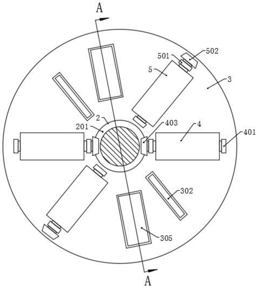
[0031] On the basis of Embodiment 1, it also includes a second rolling roller 5, the two ends of the second rolling roller 5 are rotatably connected with a second fixed rod 501, and the top of the second fixed rod 501 is connected to the rotating box 3 The bottom surface of the bottom box 1 is fixedly connected, the outer end of the second rolling roller 5 is fixedly connected with a second bevel gear 502, and the top of the bottom box 1 is uniformly provided with first teeth 105 along the circumferential direction, and the first teeth 105 and The second bevel gear 502 meshes, and when the rotating box 3 rotates, the second bevel gear 502 meshes with the first teeth 105 on the bottom case 1 to make the second rolling roller 5 rotate around the support column 2 while rotating, and the first The rolling rollers 4 roll the biomass together.

[0032] Wherein, the distance between the bottom of the first rolling roll 4 and the fixed plate 101 is greater than the distance between th...

Embodiment 3

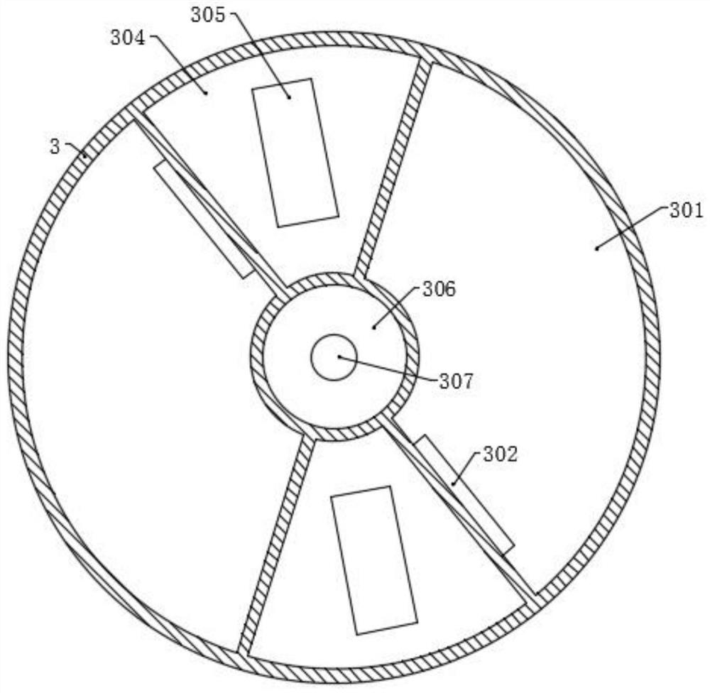
[0034]On the basis of the second embodiment, the rotating box 3 is provided with a storage chamber 301, the bottom surface of the storage chamber 301 is provided with a discharge port 302, and the rotating box 3 is also provided with a power chamber 304, the power chamber 304 The bottom surface of the bottom surface is provided with a telescopic opening 305, and a cleaning mechanism 6 is provided in the power chamber 304. The opposite direction is arranged in turn, and the biomass is added through the outlet 302 box fixed plate 101, and then rolled by the first rolling roller 4 and the second rolling roller 5 in turn, after the rolling, the biomass is removed from the fixed plate 101 Remove, and then further clean up the residual biomass on the fixed plate 101 by the cleaning mechanism 6 .

[0035] Wherein, the cleaning mechanism 6 includes a moving plate 603 and a cleaning scraper 601, two connecting rods 602 are symmetrically fixed on the bottom surface of the moving plate 6...


PUM


Abstract

The invention discloses a biomass rolling dehydration device in the technical field of biomass processing, including a bottom box, a support column, a rotating box, a first rolling roller, a second rolling roller and a cleaning mechanism. Make the rotating box rotate around the support column with the first rolling roller, and through the meshing of the first bevel gear and the second teeth in the annular groove, the first rolling roller rotates around the supporting column while rotating, so as to fix the The biomass on the plate is rolled and dehydrated; the biomass on the fixed plate is rolled for the first time by the first rolling roller, and then the second rolling is carried out by the second rolling roller to improve the effect of rolling and dehydration; Add biomass to the fixed plate of the mouth box. After the rolling, remove the biomass from the fixed plate, and then use the cleaning mechanism to further clean the residual biomass on the fixed plate. After the initial cleaning of the cleaning scraper, use the cleaning brush Secondary cleaning to make the cleaning effect better.

Description

technical field [0001] The invention relates to the technical field of biomass processing, in particular to a biomass rolling dehydration device. Background technique [0002] Biomass energy is a renewable resource. Biomass energy can be regenerated through photosynthesis of plants. It belongs to renewable energy like wind energy and solar energy. Material energy, replacing fossil fuels with biomass fuels has great benefits in reducing the greenhouse effect, and the environmental protection and ecological effects are outstanding. [0003] Biomass energy can exist in the form of biogas, compression molding solid fuel, gasification to produce gas, gasification to generate electricity, production of fuel alcohol, pyrolysis to produce biodiesel, etc., and is used in various fields of the national economy. Biomass solid fuel is formed by pulverizing biomass and adding molding to form briquettes, carbon blocks, etc., which are used as household or industrial fuels. However, the ...

Claims


Application Information

Patent Timeline
Patent Type & Authority Patents(China)
IPC IPC(8): B30B9/20B30B15/00
CPCB30B9/20B30B15/0082B30B11/228
Inventor 张祥成
Owner 绍兴卿荣针纺有限公司
Why Eureka
Try Eureka