
Automatic air column roll material cutting robot for express packaging

A technology of automatic cutting and robotics, which is applied in the directions of packaging, transportation and packaging, and containers to prevent mechanical damage. It can solve the problems of manual cutting of air column coil materials, easy deviation of position knives, and high labor intensity, so as to achieve short time consumption. , low cost and low labor intensity

Active Publication Date: 2018-11-23
张杰
View PDF6 Cites 3 Cited by
  • Summary
  • Abstract
  • Description
  • Claims
  • Application Information

AI Technical Summary

Problems solved by technology

[0003] In order to solve the above problems, the present invention provides an automatic cutting robot for air column coils used in express packaging, which can solve the need for manual cutting of existing air column coils. When cutting, personnel need to take the air column coils with one hand and carry out Cutting, because the air column coil material is not in a tight state, the cutter is easy to deviate from the position so that the knife cuts the air column coil, and the personnel may cut themselves due to operation errors when using the props. The process takes a long time, labor intensity and efficiency For low-level problems, the function of automatic cutting of the air column coil can be realized, and the position of the air column coil can be automatically limited to ensure that the air column coil is in a tight state, and it will not deviate from the position when cutting, and the air column coil can be protected during work. No manual operation is required, which ensures the safety of personnel, takes less time, and has the advantages of simple operation, low labor intensity and high work efficiency.

Method used


Image

  • Automatic air column roll material cutting robot for express packaging
  • Automatic air column roll material cutting robot for express packaging
  • Automatic air column roll material cutting robot for express packaging

Examples


Embodiment Construction

[0022] In order to make the technical means, creative features, goals and effects achieved by the present invention easy to understand, the present invention will be further described below in conjunction with specific illustrations. It should be noted that, in the case of no conflict, the embodiments in the present application and the features in the embodiments can be combined with each other.

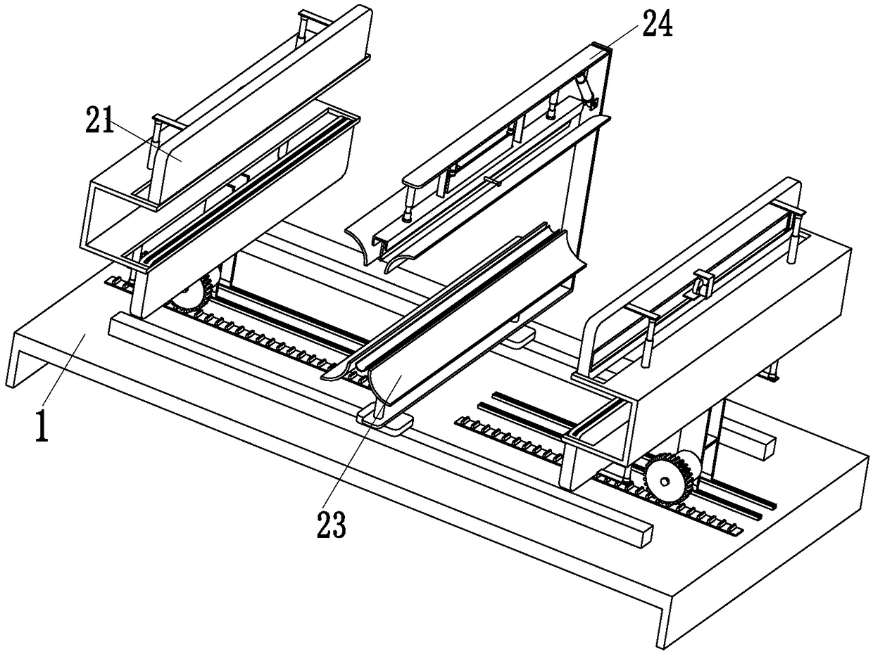
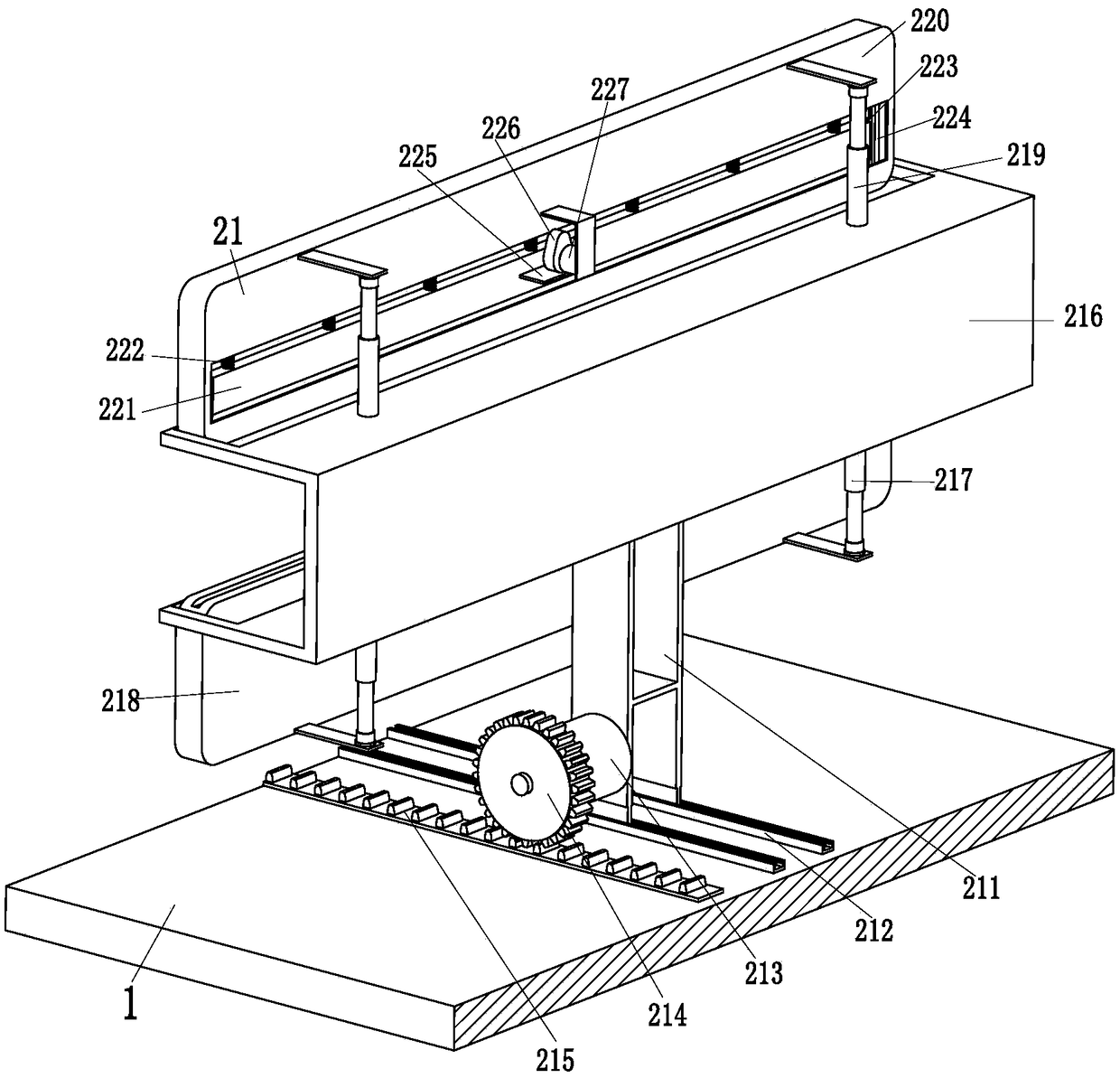
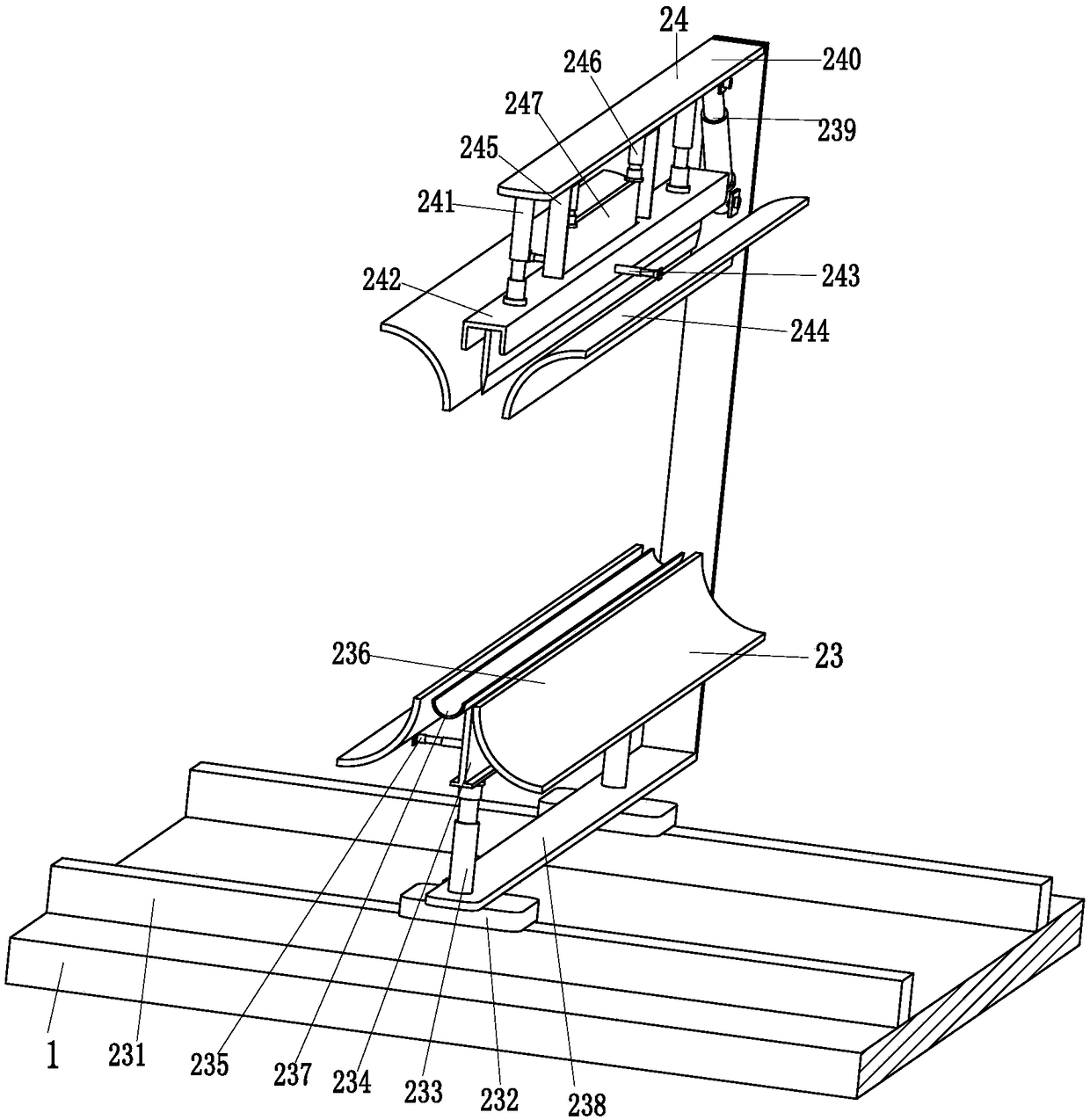
[0023] Such as Figure 1 to Figure 4 As shown, an air column automatic cutting robot for express packaging includes a U-shaped bracket 1, two limit cutting mechanisms 21, an auxiliary mechanism 23 and a cutting mechanism 24, and the two limit cutting mechanisms 21 Installed on the left and right ends of the U-shaped bracket 1, the auxiliary mechanism 23 is installed in the middle of the U-shaped bracket 1, and the upper end of the auxiliary mechanism 23 is equipped with a cutting mechanism 24.

[0024]The limit cutting mechanism 21 includes an H-shaped carriage 211, a connecting chu...


PUM


Abstract

The invention relates to an automatic air column roll material cutting robot for express packaging. The robot comprises a U-shaped support, two limit cutting mechanisms, an auxiliary mechanism and a cutting mechanism. The two limit cutting mechanisms are installed at the left and right ends of the U-shaped support, the auxiliary mechanism is installed in the middle of the U-shaped support, and thecutting mechanism is installed at the upper end of the auxiliary mechanism. According to the automatic air column roll material cutting robot for express packaging, the problems can be solved that anexisting air column roll material needs to be manually cut, during cutting, a worker needs to take the air column roll material by one hand and cut the air column roll material by the other hand, dueto the fact that the air column roll material is not in a tensioned state, a cutter easily deviates from the position, and as a result the cutter cuts through the air column roll; when using the cutter, the worker can be possibly cut and hurt due to misoperation, the consumed time is long, the labor intensity is high, and the efficiency is low; the function can be achieved that the air column roll material is automatically cut off.

Description

technical field [0001] The invention relates to the technical field of express packaging and transportation, in particular to an air column automatic cutting robot for express packaging. Background technique [0002] The modern express delivery industry is developing rapidly, and the protection of packaging products is an important service in the express delivery industry. Cushion packaging is commonly used in protective packaging, and the products studied in cushion packaging are fragile products, mainly electronic and electrical products. In cushioning packaging technology, air column coil is a new packaging system filled with natural air. The main purpose of the air column coil is the packaging and transportation of products. Its main function is to cushion and protect the packaged items. The air column coil is filled with air to form a protective layer with a certain thickness and support strength. When used, it can be fully or Partially wrap the product to minimize the...

Claims


Application Information

Patent Timeline
Patent Type & Authority Applications(China)
IPC IPC(8): B65B61/06B65D81/05
CPCB65B61/06B65D81/052
Inventor 范满香
Owner 张杰
Learn More