
A Design Method of Textured Interference-Joint Face Group

A design method and connection surface technology, applied in the direction of connection components, shrinkage connection, mechanical equipment, etc., can solve the problem of large stress concentration on the mating surface, and achieve the effect of improving contact stiffness, strength, and overall performance

Active Publication Date: 2021-04-20
XI AN JIAOTONG UNIV
View PDF5 Cites 0 Cited by
  • Summary
  • Abstract
  • Description
  • Claims
  • Application Information

AI Technical Summary

Problems solved by technology

The traditional interference connection has disadvantages such as large stress concentration at the edge of the mating surface

Method used


Image

  • A Design Method of Textured Interference-Joint Face Group
  • A Design Method of Textured Interference-Joint Face Group
  • A Design Method of Textured Interference-Joint Face Group

Examples


Embodiment 1

[0032] The connection surface group composed of the outer circle of the pin shaft and the inner circle of the pin hole is the most common interference connection of mechanical equipment. The following is combined with the attached Figure 4 The present invention will be further described by taking a square textured pin shaft as an example.

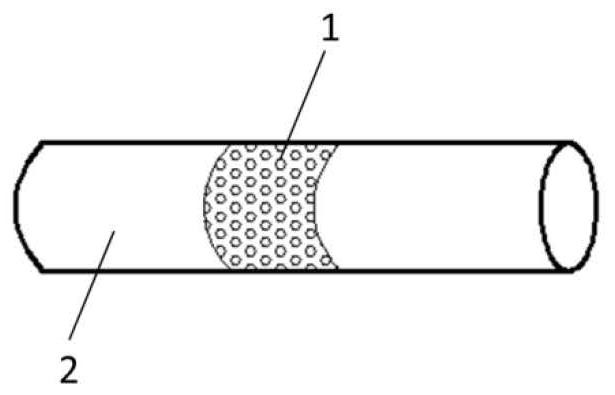
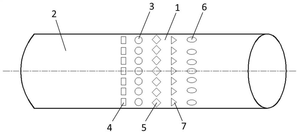
[0033] In the present invention, a textured area 1 and an untextured area 2 are designed on the interference fit connection surface formed by the pin shaft and the pin hole.

[0034] The texture zone is only designed on the outer circular mating surface of the pin shaft (see Figure 4 )superior.

[0035] The textured area 1 is provided with square pits 3 .

[0036] The square pits 3 are arranged in rows and columns parallel to the axial direction of the pin axis (ie 0°).

[0037] The geometric parameters of the square pit 3 are: the side length is 10-500um, and the depth is 2-50um.

[0038] The distance between adjacent square pits in ...


PUM


Abstract

The invention discloses a method for designing a textured interference connection face group. The connection mating surface includes a textured area and an untextured area; the textured area is only designed on the outer circular mating surface of the connecting face group, or It is only designed on the inner circle mating surface of the connecting face group, or it is designed on the outer circle mating surface and the inner circle mating surface of the connecting face group at the same time; the texture area is designed with circular pits, square pits, and rhombus pits , elliptical pits, triangular pits or any combination of several types of pits; the pit textures are arranged in rows and columns parallel to the axial direction of the connecting face group or at a certain angle. The present invention designs a concave texture on the mating surface of the interference connection, changes the contact characteristics of the mating surface, can improve the binding force of the interference connection, and effectively improves the comprehensive performance of the interference connection.

Description

technical field [0001] The invention relates to a connection joint surface, in particular to a design method for a textured interference connection surface group. Background technique [0002] Interference connection is widely used in mechanical equipment because of its simple connection structure, good centering accuracy, high bearing capacity, and can withstand torque, axial force or the combined load of the two. There are mainly two types of interference fit connection: cylindrical surface interference fit connection and conical surface interference fit connection. The traditional interference connection has disadvantages such as large stress concentration at the edge of the mating surface. Contents of the invention [0003] The present invention aims at the deficiencies of the prior art, and aims at proposing a method for designing a textured interference connection surface group. By designing a concave texture on the interference connection mating surface, the contac...

Claims


Application Information

Patent Timeline
Patent Type & Authority Patents(China)
IPC IPC(8): F16B4/00F16F15/02
CPCF16B4/004F16F15/02
Inventor 林起崟洪军王继红刘正朱林波
Owner XI AN JIAOTONG UNIV
Learn More