Spiral plate heat exchanger with protection function for sludge and working method thereof

A heat exchanger and spiral plate technology, applied in the field of spiral plate heat exchangers for sludge, can solve the problems of increasing maintenance and equipment investment costs, affecting the work of the heat exchange system, and easily blocking the sludge, and achieving good protection effects. , the effect of alleviating friction and reducing the amplitude of oscillation

Inactive Publication Date: 2018-11-23
SUZHOU SHUIMUKANGQIAO ENVIRONMENTAL ENG TECH CO LTD
View PDF8 Cites 1 Cited by
  • Summary
  • Abstract
  • Description
  • Claims
  • Application Information

AI Technical Summary

Problems solved by technology

Sludge heat treatment technology is constantly updated and developed, but the problem of highly toxic dioxins, the problem of odor emission and tail gas treatment in the process of sludge drying, and the problem of high energy consumption in heat treatment are becoming more and more prominent
[0004] Moreover, in the existing sludge heat treatment process, because the heat-treated sludge is prone to clogging in the later flow process, it cannot circulate, which affects the work of the entire heat exchange system and increases maintenance and equipment investment costs.

Method used


Image

  • Spiral plate heat exchanger with protection function for sludge and working method thereof
  • Spiral plate heat exchanger with protection function for sludge and working method thereof
  • Spiral plate heat exchanger with protection function for sludge and working method thereof

Examples


Embodiment 1

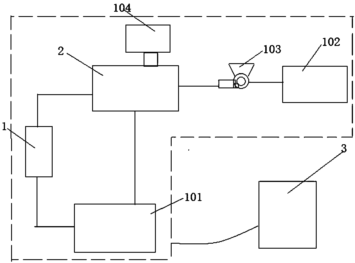
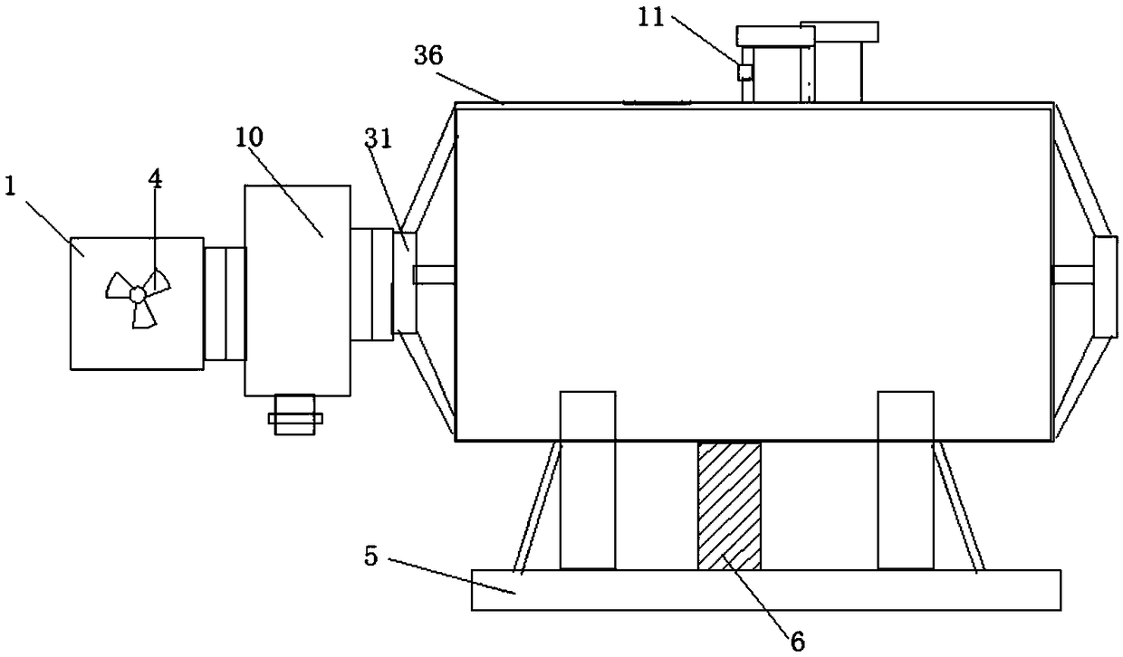
[0042] A spiral plate heat exchanger with protective function described in this embodiment includes: a feeding device 1, a heat exchanger 2 and a control device 3, and the feeding device 1 is provided with a stirring device 4 , the input end of the feeding device 2 is connected to the sludge heat processor 101 through a pipeline, the outlet end of the feeding device 2 is connected to the heat exchanger 2, and a fixing frame 5 is provided under the heat exchanger 2 , the fixed frame 5 is provided with a shock absorbing mechanism 6, the output end of the heat exchanger 2 is connected to the heat recovery mechanism 102 through a pipeline, and a circulating fan is arranged between the heat exchanger 2 and the heat recovery mechanism 102 103;

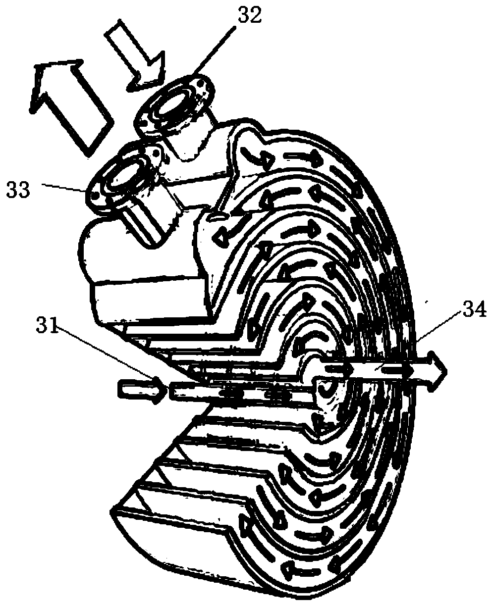
[0043] The heat exchanger 2 adopts a spiral plate exchange structure, and is made of two groups of metal plates rolled into a spiral plate shape to form two circulation paths, in which there are two circulation paths, namely the first circul...

Embodiment 2

[0046] A spiral plate heat exchanger with protective function described in this embodiment includes: a feeding device 1, a heat exchanger 2 and a control device 3, and the feeding device 1 is provided with a stirring device 4 , the input end of the feeding device 2 is connected to the sludge heat processor 101 through a pipeline, the outlet end of the feeding device 2 is connected to the heat exchanger 2, and a fixing frame 5 is provided under the heat exchanger 2 , the fixed frame 5 is provided with a shock absorbing mechanism 6, the output end of the heat exchanger 2 is connected to the heat recovery mechanism 102 through a pipeline, and a circulating fan is arranged between the heat exchanger 2 and the heat recovery mechanism 102 103;

[0047] The heat exchanger 2 adopts a spiral plate exchange structure, and is made of two groups of metal plates rolled into a spiral plate shape to form two circulation paths, in which there are two circulation paths, namely the first circul...

Embodiment 3

[0053] A spiral plate heat exchanger with protective function described in this embodiment includes: a feeding device 1, a heat exchanger 2 and a control device 3, and the feeding device 1 is provided with a stirring device 4 , the input end of the feeding device 2 is connected to the sludge heat processor 101 through a pipeline, the outlet end of the feeding device 2 is connected to the heat exchanger 2, and a fixing frame 5 is provided under the heat exchanger 2 , the fixed frame 5 is provided with a shock absorbing mechanism 6, the output end of the heat exchanger 2 is connected to the heat recovery mechanism 102 through a pipeline, and a circulating fan is arranged between the heat exchanger 2 and the heat recovery mechanism 102 103;

[0054] The heat exchanger 2 adopts a spiral plate exchange structure, and is made of two groups of metal plates rolled into a spiral plate shape to form two circulation paths, in which there are two circulation paths, namely the first circul...


PUM


Abstract

The invention discloses a spiral plate heat exchanger with a protection function for sludge and a working method thereof. The spiral plate heat exchanger comprises a feeding device, a heat exchanger and a control device, wherein a stirring device is arranged in the feeding device; the input end of the feeding device is connected with a sludge heat processor through a pipeline; the outlet end of the feeding device is connected with the heat exchanger, a fixing frame is arranged below the heat exchanger, a damping mechanism is arranged on the fixing frame, and the output end of the heat exchanger is connected with a heat recovery mechanism through a pipeline; the heat exchanger uses a spiral plate exchange structure, two flow paths are arranged in the structure, the two paths are respectively a first flow path and a second flow path, and the feeding device, the heat exchanger and the stirring device are all connected with the control device. According to the invention, the stirring device in arranged in the feeding device to stir the sludge to prevent the sediments in the sludge from causing clogging of the flow paths, and the exchanged heat energy is transmitted to the heat recoverymechanism to supply heat to the equipment requiring heat energy, and the arrangement of the shock absorbing mechanism can effectively reduce the oscillation amplitude of the heat exchanger.

Description

technical field [0001] The invention belongs to the technical field of sludge treatment, and in particular relates to a spiral plate heat exchanger for sludge with protection function and a working method thereof. Background technique [0002] With the rapid development of social economy, people's living standards and quality of life are constantly improving, and whether it is production or life, people's rhythm is constantly accelerating, the requirements for the environment are getting higher and higher, and production is gradually Realized automation and intelligence. With the realization of automation and intelligence, more and more energy is consumed, which leads to the birth of energy recovery. [0003] With the in-depth study of sludge microcosm and the continuous development of application technology in recent years, sludge heat treatment technology is receiving unprecedented attention. From the earliest sludge firing ceramics and brick making technology to the pre...

Claims


Application Information

Patent Timeline
Patent Type & Authority Applications(China)
IPC IPC(8): F28D9/04F28F19/01F28F27/00F28F9/00C02F11/00C02F11/12
Inventor 李剑峰
Owner SUZHOU SHUIMUKANGQIAO ENVIRONMENTAL ENG TECH CO LTD
Why Eureka
Try Eureka