Hydrologic monitoring device

A technology of hydrological monitoring and water inlet, applied in the direction of buoy liquid level indicator, etc., can solve the problems of inaccurate structure, jamming, large resistance, etc., achieve the effect of objective and accurate recording, and reduce resistance and error

Active Publication Date: 2018-11-23
FORESTRY RES INST OF HEILONGJIANG PROVINCE
View PDF6 Cites 3 Cited by
  • Summary
  • Abstract
  • Description
  • Claims
  • Application Information

AI Technical Summary

Problems solved by technology

The lowest water level of rivers and lakes, the lowest tide level of beaches, and the lowest water level of ditches are important parameters for river and lake health assessment, beach development planning and channel water consumption calculation. Traditional measurement methods are expensive and inconvenient
[0004] Hydrological monitoring devices in the prior art, such as a magnetic suction type open channel minimum water level self-recording ruler and its method disclosed in the Chinese invention patent No. CN201310423676.7, but it has some disadvantages, 1. The resistance of the ring is too large, so that the ring cannot move up smoothly, and the final structure is inaccurate; 2. The shape of the floating block and the cylinder are compatible, and there will be jamming due to the deviation of its stroke; 3. The sewage in the river Too much mud and weeds, etc., will cause debris to accumulate in the device, affecting its normal use

Method used


Image

  • Hydrologic monitoring device
  • Hydrologic monitoring device
  • Hydrologic monitoring device

Examples


Embodiment Construction

[0029] In order to make the purpose, technical solution and advantages of the present invention clearer, the invention will be clearly and completely described below in conjunction with the accompanying drawings and specific embodiments.

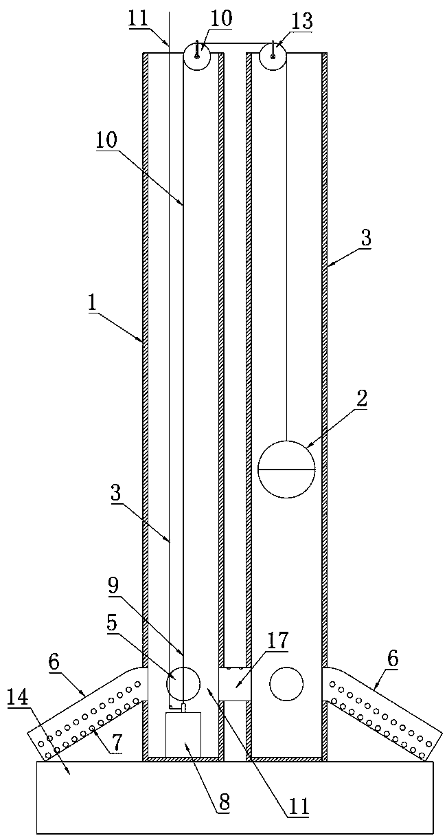
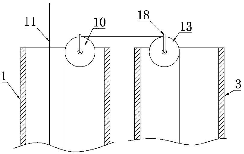
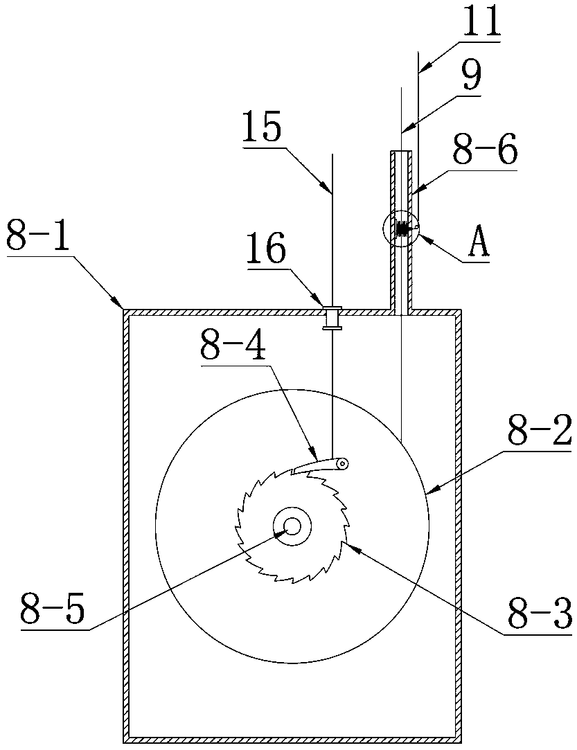
[0030] Such as Figure 1-5 The shown hydrological monitoring device includes a cylindrical first cylinder body 1 and a second cylinder body 3 arranged side by side. The bottom of the first cylinder body 1 is fixedly provided with a one-way pay-off mechanism 8 . A floating ball 2 is arranged inside the second cylinder 3 , and the diameter of the floating ball 2 is smaller than the inner diameter of the second cylinder 3 , so that the floating ball 2 will not be blocked and frictional when moving in the second cylinder 3 . Preferably, the inner wall of the second cylinder 3 is provided with polytetrafluoroethylene coating, which can ensure the smoothness of the inner wall of the cylinder, reduce sludge adhesion, and prevent the cylinder from r...


PUM


Abstract

The invention relates to a hydrologic monitoring device. The device includes a first drum body and a second drum body which are cylindrical and are arranged side by side; a unidirectional unwinding mechanism is fixedly arranged at the bottom of the first drum body, a floating ball is arranged in the second drum body, the diameter of the floating ball is smaller than the inner diameter of the second drum body, and multiple water inlets are formed in the lower portions of the first drum body and second drum body; a protection device is arranged at the exterior of each water inlet, and the unidirectional unwinding mechanism includes a housing, a rotating shaft arranged in the housing and a first winding wheel fixedly arranged on the rotating shaft. The two ends of the rotating shaft are connected to the housing through bearings, a ratchet wheel is also fixedly arranged on the rotating shaft, a pawl matched with the ratchet wheel is arranged in the housing, and a first pull line is arranged on the first winding wheel. A first pulley is arranged on the top of the first drum body, a second pulley is arranged on the top of the second drum body, and the top of the first pull line sequentially bypasses the first pulley and the second pulley to be connected to the top of the floating ball.

Description

technical field [0001] The invention relates to an indicating or measuring device for a liquid level or a flowing solid material level, in particular to a hydrological monitoring device. Background technique [0002] At present, the following two methods are generally used for river water level measurement, the traditional water gauge and the electronic water level gauge. The traditional water gauge is a scale with a scale set in the river channel. With the change of the water level in the river channel, a special person will read the real-time water level. Modern hydrological surveys use electronic technology water level gauges, mainly including float type, bubble type, radar type, etc., all of which require special equipment for data collection and transmission, and are generally set up in special hydrological stations and water level measuring stations. [0003] At present, the water level measurement of open waters generally uses traditional water gauges for manual trac...

Claims


Application Information

Patent Timeline
Patent Type & Authority Applications(China)
IPC IPC(8): G01F23/42G01F23/76
CPCG01F23/42G01F23/76
Inventor 蒙宽宏姚佳邢亚娟郭树平张妍妍曹焱张文达李海霞张海峰王岩
Owner FORESTRY RES INST OF HEILONGJIANG PROVINCE
Why Eureka
Try Eureka