
Low temperature valve low temperature test clamping device and method thereof

A low-temperature test and clamping device technology, which is applied in the direction of workpiece clamping devices, measuring devices, and testing of mechanical components, can solve the problems of increasing the complexity of test operations, low test efficiency, and high labor intensity, so as to improve the low-temperature test. Efficiency, reduction of operation complexity, and improvement of disassembly efficiency

Active Publication Date: 2018-11-23
SHANGHAI MICROPOWERS
View PDF13 Cites 4 Cited by
  • Summary
  • Abstract
  • Description
  • Claims
  • Application Information

AI Technical Summary

Problems solved by technology

[0005] (1) During the rapid cooling process of the screw clamping flange and valve, large cold shrinkage deformation occurs, and the pre-tightening clamping force of the sealing gasket changes , easily lead to seal failure;
[0006](2) The screw clamping flange must be manually disassembled and clamped, which is labor intensive and the test efficiency is low. When the valve is heavy, special lifting tools are required Lifting and dipping further increases the complexity of the test operation;
[0007] (3) The clamping force transmitted by the screw in the screw clamping flange is difficult to keep consistent, and the valve interface is prone to dislocation clamping. After the sealing gasket is crooked, the clamping Leakage is not guaranteed
Repeated disassembly and adjustment will further reduce test efficiency and increase labor costs and production cycles;
[0008] (4) When the screw clamping flange is immersed in the cryogenic tank, if there is no mechanical assistance such as automatic hoisting, it must be manually dragged and impregnated. human safety hazard

Method used


Image

  • Low temperature valve low temperature test clamping device and method thereof
  • Low temperature valve low temperature test clamping device and method thereof
  • Low temperature valve low temperature test clamping device and method thereof

Examples


Embodiment Construction

[0053] In order to more clearly illustrate the embodiments of the present invention or the technical solutions in the prior art, the specific implementation manners of the present invention will be described below with reference to the accompanying drawings. Obviously, the accompanying drawings in the following description are only some embodiments of the present invention, and those skilled in the art can obtain other accompanying drawings based on these drawings and obtain other implementations.

[0054] In order to make the drawing concise, the parts related to the present invention are only schematically shown in each drawing, and they do not represent the actual structure of the product. In addition, to make the drawings concise and easy to understand, in some drawings, only one of the components having the same structure or function is schematically shown, or only one of them is marked. Herein, "a" not only means "only one", but also means "more than one". In this arti...


PUM


Abstract

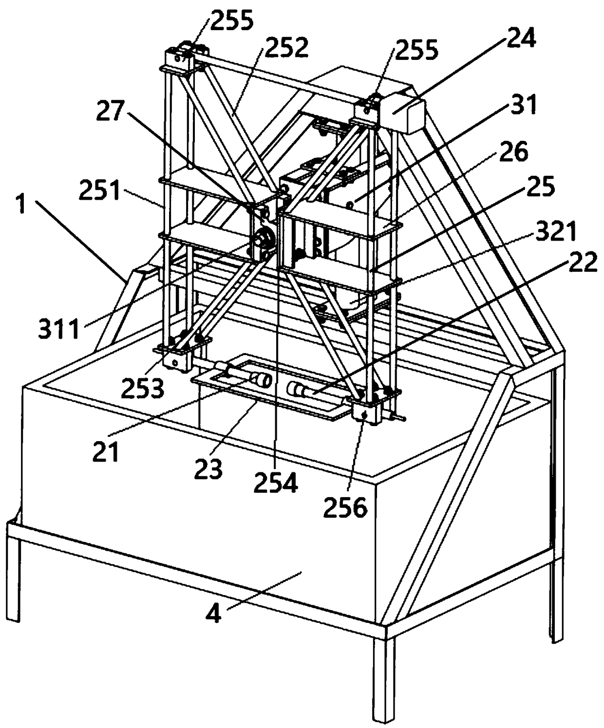
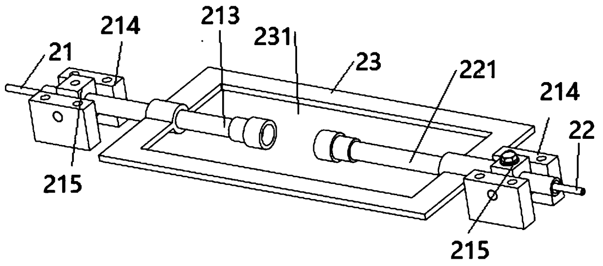
The invention discloses a low temperature valve low temperature test clamping device and a method thereof; the low temperature valve low temperature test clamping device comprises a clamping mechanismand a lifting mechanism; the clamping mechanism comprises a pair of interface clamp sleeves arranged in opposite and used for sealing and jointing with interfaces of a low temperature valve; the clamping mechanism also comprises a counterweight limit frame plate, wherein the first and second interface clamp sleeves are arranged in opposite with respect to the counterweight limit frame plate so asto clamp the low temperature valve in a hollow portion of the counterweight limit frame plate; the clamping mechanism also comprises a cylinder used for driving the first and second interface clamp sleeves to mutually get away from each other or get close to each other; the lifting mechanism is used for driving the clamping mechanism to get away from or get close to a cooling tank. The clamping device provides a constant clamping force via a pneumatic mode, thus ensuring the interfaces clamping the low temperature valve to seal up after cold shrinkage deformation, ensuring the clamping sealing performance of the valve in a temperature fast and greatly dropping process, and improving the valve low temperature test dismounting efficiency.

Description

technical field [0001] The invention relates to the technical field of low-temperature valve testing, in particular to a low-temperature valve low-temperature test clamping device and a method thereof. Background technique [0002] Ultra-low temperature valves refer to valves that can be used at temperatures below -40°C. They are important cut-off devices in circulation pipelines for low-temperature media such as ethylene, liquid oxygen, and liquefied natural gas. An important component for product explosion and leakage. Therefore, the national standard puts forward special requirements for the inspection of ultra-low temperature valves. In addition to meeting the same performance requirements as general-purpose valves at room temperature, performance tests under low temperature conditions are also required to test the performance of ultra-low temperature valves in low temperature environments. overall machine performance. Therefore, the low temperature test device is very...

Claims


Application Information

Patent Timeline
IPC IPC(8): G01M13/00B25B11/00
CPCG01M13/00B25B11/00
Inventor 苏晨光林志民杜柯江
Owner SHANGHAI MICROPOWERS
Learn More