Wire cable conductor DC resistance auxiliary measuring device and measuring method

A DC resistance, wire and cable technology, applied in the direction of measuring devices, measuring electrical variables, measuring resistance/reactance/impedance, etc., can solve problems such as single-line non-passing current, affecting length measurement accuracy, and limited measurement length, so as to solve the preparatory work Complicated and cumbersome, accurate length measurement results, and the effect of improving measurement accuracy

Inactive Publication Date: 2018-11-23
ELECTRIC POWER RESEARCH INSTITUTE OF STATE GRID SHANDONG ELECTRIC POWER COMPANY +1
View PDF9 Cites 3 Cited by
  • Summary
  • Abstract
  • Description
  • Claims
  • Application Information

AI Technical Summary

Problems solved by technology

The four-terminal measurement fixture has the following problems: On the one hand, since the contact resistance is the most important factor affecting the measurement results, the surface of the measured wire and cable is always exposed to the air and gradually forms an oxide layer, which is different from the resistivity of the tested conductor , after the wire and cable are connected to the fixture, the resistance generated by the oxide layer changes with the thickness of the oxide layer, the contact area and other factors, making the measurement result inaccurate; The length between wires and cables will inevitably have a certain bending phenomenon. The cable needs to be straightened, but there must be no distortion that causes the cross-section of the cable conductor to change. The four-terminal measuring fixture potential for measuring wires and cables on the market The electrode is generally fixed at 1 meter, and the measurement length is very limited, which affects the accuracy of length measurement
For example, the current lead-in end of the aluminum stranded wire is crimped with a copper or aluminum crimping joint, so that the conductor and the joint are integrated after crimping, and then placed in a four-terminal measuring fixture for measurement. This measurement method has achieved certain results, but The crimping process of the sample is time-consuming and laborious, and the production effect has a lot to do with the proficiency of the operator
Chinese patent document 201210070556.9 "Cable Conductor DC Resistance Test Device", adopts the end surface current input method to test the cable conductor DC resistance, and allows the test current to enter the end surface of the conductor directly from the end surface current input fixture through the current lead, reducing the contact resistance between the conductor and the fixture , which improves the measurement accuracy, but the device has the following problems: it is difficult to ensure one-to-one alignment between the top of the current introduction terminal and the end face of the cable conductor, and it is also difficult to maintain the same contact force, which may easily cause some single wires to fail to pass the current and the test is inaccurate
Chinese patent document 201210401556.2 "Cable Conductor DC Resistance Test Device and Test Method", adopts the method of increasing the length of the tested sample and layered current input method to test the DC resistance of the conductor, reducing the impact of contact resistance on the test results and improving the accuracy of the test , but this method needs to peel off layers of conductors to expose each layer of conductors. The processing process is complicated and it is easy to cause damage to the inner layer conductors. Cable samples with short lengths

Method used


Image

  • Wire cable conductor DC resistance auxiliary measuring device and measuring method
  • Wire cable conductor DC resistance auxiliary measuring device and measuring method
  • Wire cable conductor DC resistance auxiliary measuring device and measuring method

Examples


Embodiment Construction

[0031] In order to make the content of the present invention easier to understand, the present invention will be further described in detail below based on specific embodiments and in conjunction with the accompanying drawings.

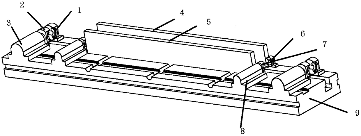
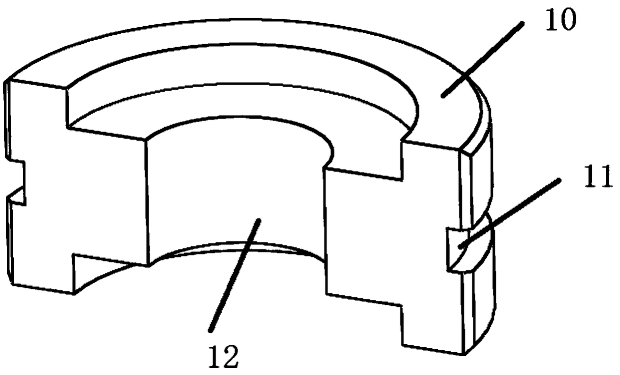
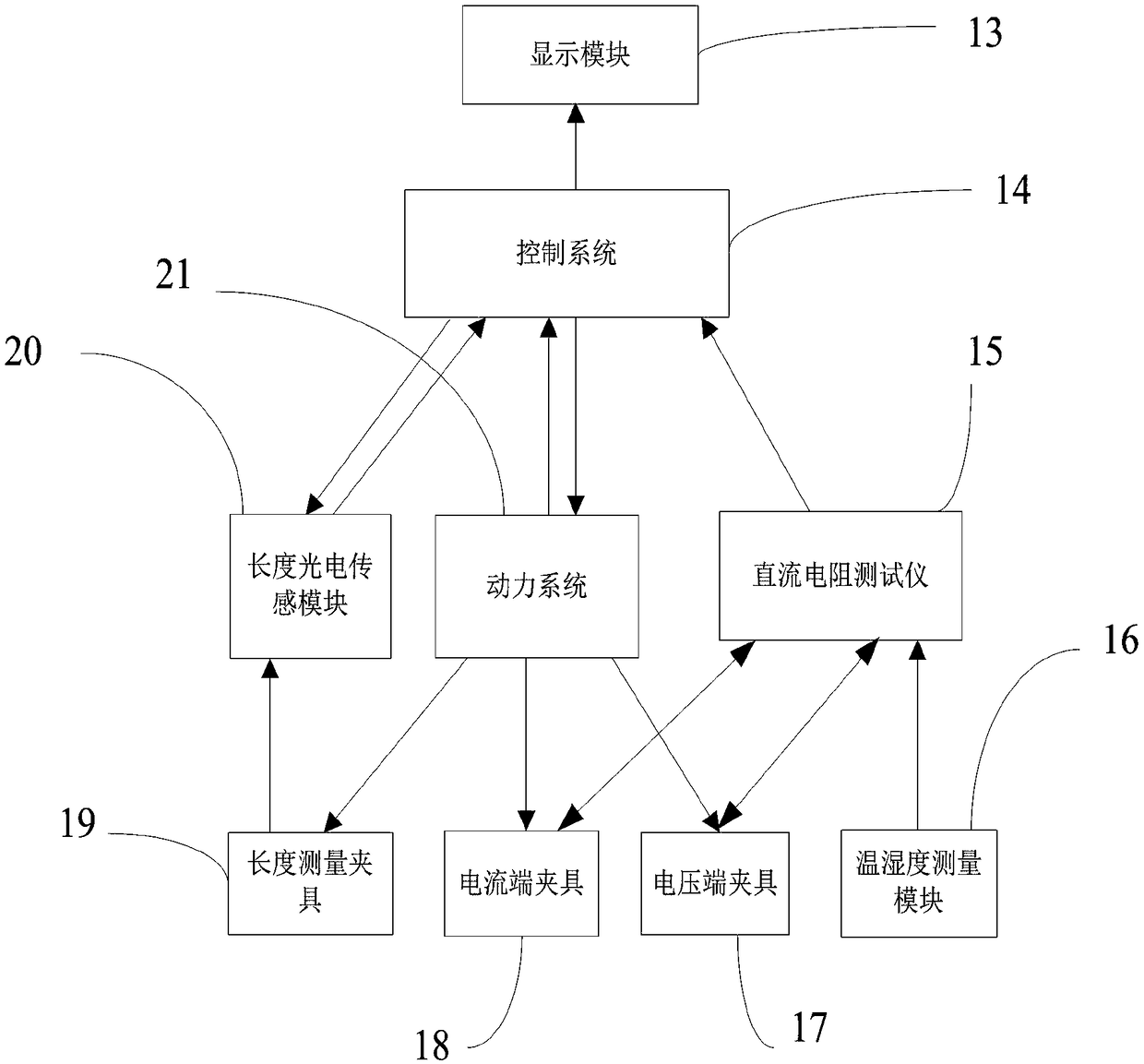
[0032] see Figure 1-Figure 3, an auxiliary measuring device for DC resistance of wire and cable conductors, comprising a current end fixture 18, a potential end fixture 17, a length measurement fixture 19, a length photoelectric sensor module 20, a temperature and humidity measurement module 16, a base 9, a power system 21, and a control system 14 and a display module 13, the current end fixture 18, the potential end fixture 17, the length measurement fixture 19, and the length photoelectric sensor module 20 are respectively connected to the base, and the control system-14 is connected with the power system-21, the length photoelectric sensor Module-20, DC resistance tester-15, and display module-13 are connected, the temperature and humidity measure...


PUM


Abstract

The invention discloses a wire cable conductor DC resistance auxiliary measuring device and a measuring method; the measuring device comprises a current terminal clamp, a potential terminal clamp, a length measuring clamp, a length photoelectric sensing module, a humiture measuring module, a pedestal, a power system, a control system and a display module; the current terminal clamp, the potentialterminal clamp, the length measuring clamp and the length photoelectric sensing module are respectively connected with the pedestal; the control system is connected with the power system, the length photoelectric sensing module, a DC resistance tester, and the display module; the humiture measuring module is connected with the DC resistance tester; the power system is respectively connected with acurrent terminal power portion of the current terminal clamp, a potential terminal power portion of the potential terminal clamp, and a clamp force application structure of a length measuring clamp II of the length measuring clamp; the current terminal power portion and the potential terminal power portion are respectively connected with the pedestal. The measuring device can improve the conductor DC resistance measuring accuracy, is convenient in operation, timesaving and labor saving, can reduce test material cost, and can improve work efficiency.

Description

technical field [0001] The invention relates to the technical field of a cable conductor DC resistance measuring device, in particular to an auxiliary measuring device and an auxiliary measuring method for a wire and cable conductor DC resistance. Background technique [0002] With the continuous progress and development of society, the insulation of urban power grids and the continuous advancement of cables, the number of wires and cables such as overhead insulated cables and power cables has increased rapidly. The important role of cables. Therefore, the performance of wire and cable is directly related to the final power consumption and production effect of the user, and the DC resistance detection of the wire and cable conductor is the most important thing. The DC resistance of wire and cable conductors is one of the important indicators to characterize the electrical performance of cables, and the conductor DC resistance test is the main means to assess the conductivit...

Claims


Application Information

Patent Timeline
Patent Type & Authority Applications(China)
IPC IPC(8): G01R27/02G01D21/02G01B21/02
CPCG01B21/02G01D21/02G01R27/02
Inventor 张围围许冬冬张建王安东赵富强许光可李星陈令英王楠王广涛
Owner ELECTRIC POWER RESEARCH INSTITUTE OF STATE GRID SHANDONG ELECTRIC POWER COMPANY
Why Eureka
Try Eureka