Diffraction coefficient solving method and device

A technology of coefficient and diffraction, which is applied in the field of diffraction coefficient solution method and device, can solve the problems that cannot truly reflect the change characteristics of diffraction waves, cannot effectively identify small structural geological bodies, and the diffraction coefficient is not accurate enough, etc.

Inactive Publication Date: 2018-11-23
CHINA UNIV OF MINING & TECH (BEIJING)
View PDF4 Cites 0 Cited by
  • Summary
  • Abstract
  • Description
  • Claims
  • Application Information

AI Technical Summary

Problems solved by technology

The conventional way to obtain the diffraction wave is to directly separate the reflection wave from the seismic wave, and the diffraction wave obtained in this way is mixed with a lot of interference waves, which is not conducive to the study of the variation characteristics of the diffraction wave produced by small structural geological bodies, and, The diffraction wave will encounter the absorption and attenuation of the underground medium during the propagation process. If the absorption and attenuation process of the diffraction wave in the formation is not taken into account in the calculation of the diffraction coefficient, the obtained diffraction coefficient will not be accurate enough and cannot be truly Reflecting the changing characteristics of diffraction waves, it cannot effectively identify small structural geological bodies, and cannot provide a more reliable basis for finding and interpreting small structural geological bodies in seismic exploration, as well as provide effective protection for the safe mining of mineral resources

Method used


Image

  • Diffraction coefficient solving method and device
  • Diffraction coefficient solving method and device
  • Diffraction coefficient solving method and device

Examples


Embodiment 1

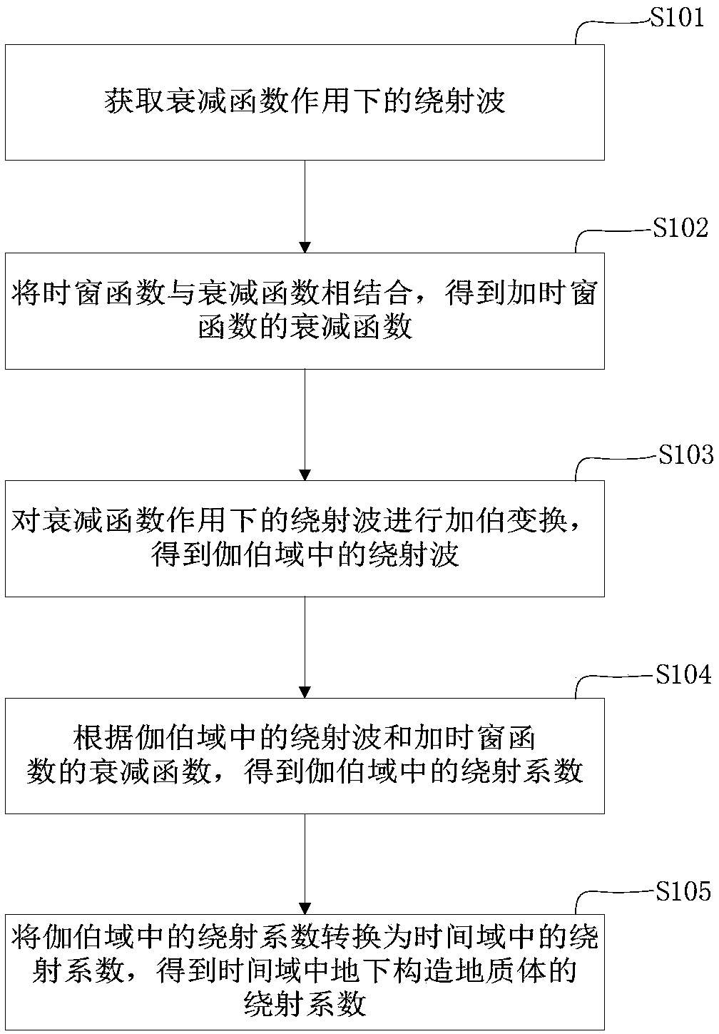
[0041] This embodiment provides a method for solving the diffraction coefficient, such as figure 1 As shown, the method includes the following steps:

[0042] Step S101: Obtain the diffracted wave under the action of the attenuation function.

[0043] Specifically, according to the principle of Gaber transformation, the diffracted wave under the action of the attenuation function is calculated. The specific expression of the unsteady diffracted wave under the constant Q attenuation function is:

[0044]

[0045] Where s Q (t) is the diffraction wave function, α Q (τ,f)=e -πfτ / Q+iH(πfτ / Q) It is the constant Q attenuation function of the underground medium, and d(τ) is the diffraction coefficient.

[0046] Step S102: Combine the time window function with the attenuation function to obtain the attenuation function of the time window function.

[0047] Introducing a time window function with a correction factor in the calculation of the attenuation function can make the diffracted wave at...

Embodiment 2

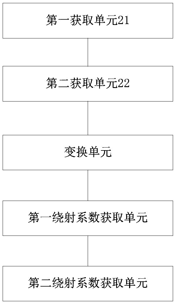
[0064] This embodiment provides a diffraction coefficient solving device, such as figure 2 As shown, the device includes:

[0065] The first obtaining unit 201 is used to obtain the diffracted wave under the action of the attenuation function.

[0066] The second obtaining unit 202 is configured to combine the time window function with the attenuation function to obtain the attenuation function of the added time window function.

[0067] Among them, the time window function is the time window function with the correction factor added. The time window function with the correction factor can make the diffracted wave attenuate differently with the propagation time of the diffracted wave during the calculation process, so that the calculation of the attenuation function is more accurate. And make the calculation of the final diffraction coefficient more accurate.

[0068] The transformation unit 203 is configured to perform a Gaber transformation on the diffracted wave under attenuation ...

Embodiment 3

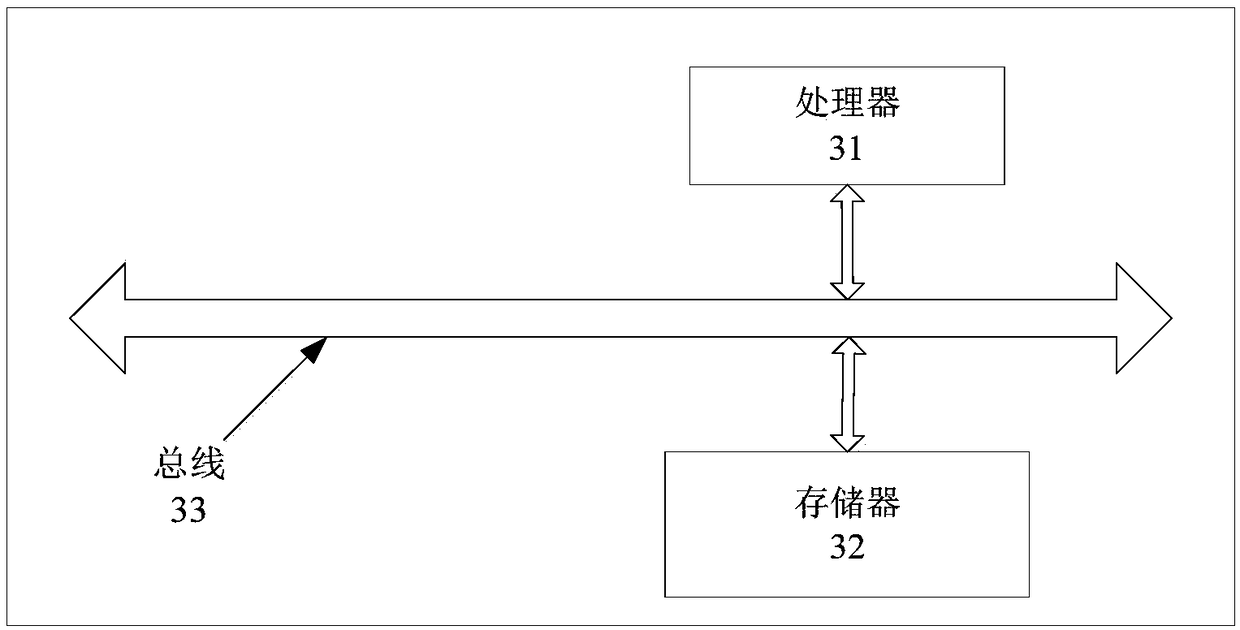
[0075] This embodiment provides a diffraction coefficient solving device, such as image 3 As shown, the device includes a processor 31 and a memory 32; where the memory 32 is used to store one or more computer instructions, and one or more computer instructions are executed by the processor to implement the above-mentioned distributed task processing method. image 3 The device shown further includes a bus 33, and the processor 31 and the memory 32 are connected via the bus 33.

[0076] The memory 32 may include a high-speed random access memory (RAM, Random Access Memory), and may also include a non-volatile memory (non-volatile memory), such as at least one disk memory. The bus 33 may be an ISA bus, a PCI bus, an EISA bus, or the like. The bus can be divided into address bus, data bus, control bus, etc. For ease of presentation, image 3 It is represented by only a two-way arrow, but it does not mean that there is only one bus or one type of bus.

[0077] The processor 31 may b...


PUM


Abstract

The invention provides a diffraction coefficient solving method and device and belongs to the seismic exploration and engineering geology technology field. The diffraction coefficient solving method is characterized by acquiring a diffraction wave under an attenuation function effect; combining a time window function with an attenuation function to acquire the attenuation function with the time window function; carrying out Gabor transform on the diffraction wave under the attenuation function effect to obtain the diffraction wave in a Gabor domain; and according to the diffraction wave in theGabor domain and the attenuation function with the time window function, acquiring a diffraction coefficient in the Gabor domain, converting the diffraction coefficient in the Gabor domain into the diffraction coefficient in a time domain, obtaining the diffraction coefficient of an underground tectonic geologic body in the time domain, and according to a Gabor transformation principle, solving the diffraction coefficient, and introducing the improved time window function into the attenuation function, and acquiring the high-precision diffraction coefficient. A reliable basis is provided foridentifying a microtectonic geologic body in seismic exploration and effective guarantee is provided for the safety exploitation of mineral product resources.

Description

Technical field [0001] The invention relates to the technical fields of geological prospecting and engineering geology, in particular to a method and device for solving diffraction coefficients. Background technique [0002] In the mining of coal, petroleum and other mineral resources, structural abnormalities such as faults, collapsed columns, and structural traps are often encountered. These abnormal bodies often lead to water channels in the coal seam, causing water inrush accidents from the roof and floor of the coal seam. The safe mining of coal mines and the safety of personnel bring dangers. If structural traps are generated near faults, the traps are easily destroyed, causing oil and gas to escape, which is not conducive to oil storage and development. Therefore, the identification of small structural anomalies is of great significance to the exploitation of mineral resources such as coal and oil. In seismic exploration, when seismic waves propagate to the underground me...

Claims


Application Information

Patent Timeline
Patent Type & Authority Applications(China)
IPC IPC(8): G01V1/28
CPCG01V1/28
Inventor 柳倩男彭苏萍赵惊涛崔晓芹
Owner CHINA UNIV OF MINING & TECH (BEIJING)
Why Eureka
Try Eureka