Artificial field source frequency domain electromagnetic apparent resistivity measuring method

A technology of apparent resistivity and artificial field source, which is applied in the field of artificial field source frequency domain electromagnetic apparent resistivity measurement, can solve problems affecting the accuracy and efficiency of apparent resistivity calculation, reduce the scope of application of CSAMT, and increase the cost of field exploration. Achieve the effects of reducing field exploration costs, avoiding poor calculation accuracy, and improving solution efficiency and accuracy

Active Publication Date: 2018-11-23
EAST CHINA UNIV OF TECH
View PDF5 Cites 19 Cited by
  • Summary
  • Abstract
  • Description
  • Claims
  • Application Information

AI Technical Summary

Problems solved by technology

For example, it still uses the conventional Carnia apparent resistivity definition method for calculation (such as or ), the premise of this definition is that electromagnetic waves propagate as plane waves, so it is necessary to place the observation area in the far area, and use the data in the far area to calculate the apparent resistivity, and the apparent resistivity calculated in the non-far area will produce serious distortion. Therefore, the data in the transition zone and the near zone are discarded, thereby reducing the scope of application of CSAMT
At the same time, working in the field needs to measure two orthogonal electric and magnet

Method used


Image

  • Artificial field source frequency domain electromagnetic apparent resistivity measuring method
  • Artificial field source frequency domain electromagnetic apparent resistivity measuring method
  • Artificial field source frequency domain electromagnetic apparent resistivity measuring method

Examples


Embodiment Construction

[0043] The following is a further description of the present invention in conjunction with the accompanying drawings and specific embodiments

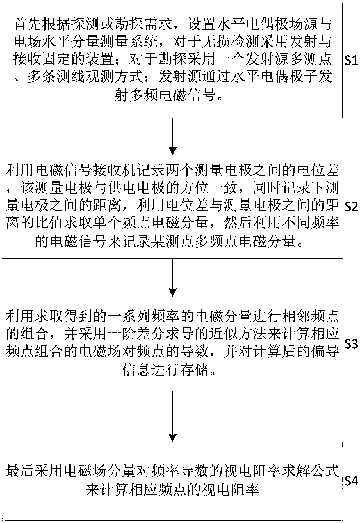
[0044] See figure 1 As shown, the present invention provides an artificial field source frequency domain electromagnetic apparent resistivity measurement method, which comprises the following steps:

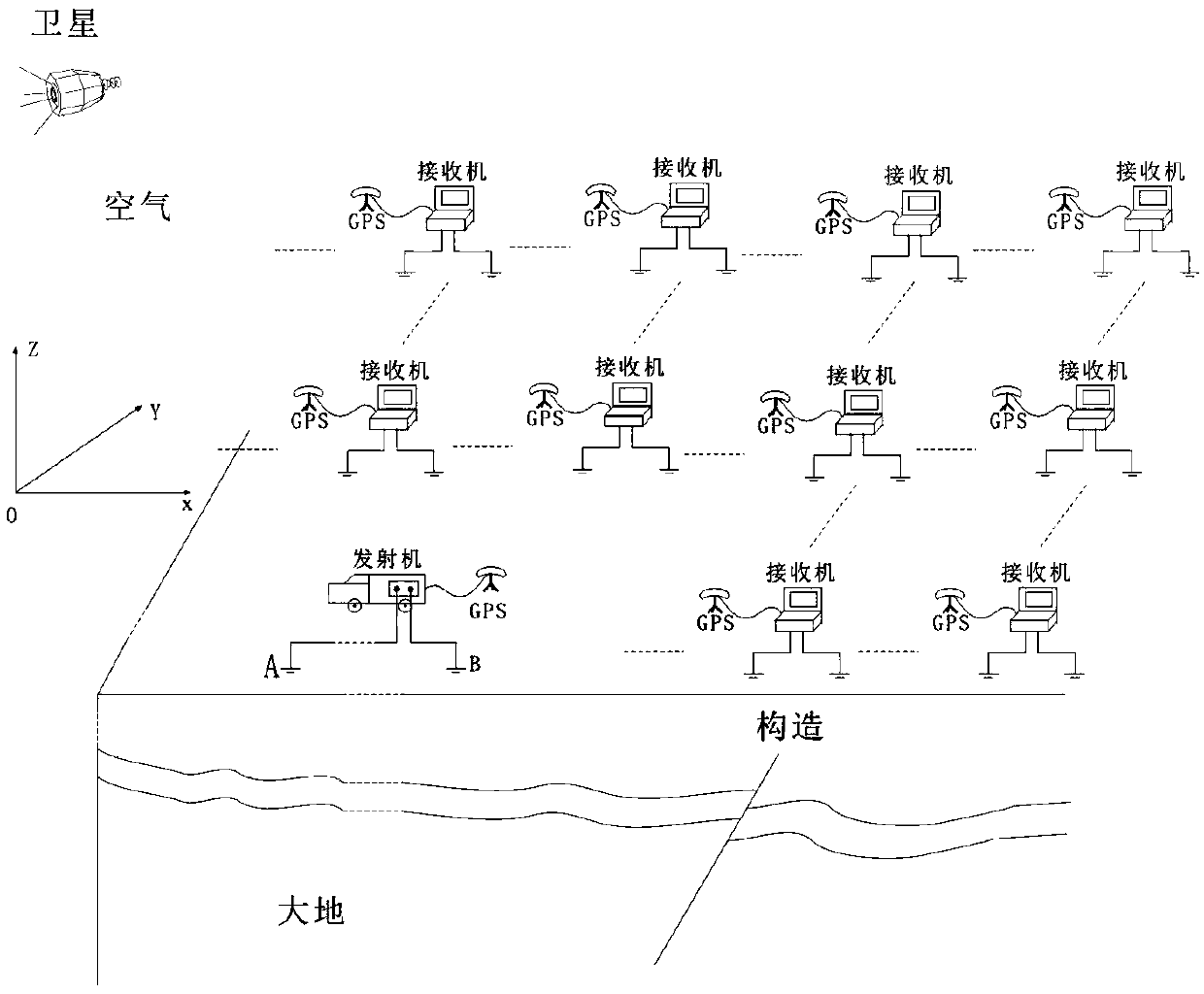
[0045] Step S1: First, according to the exploration needs, set the appropriate field source position, and lay out a number of survey lines and corresponding observation points in the exploration area, place an electromagnetic signal receiver at the observation point, and place the signal transmitter at the field source position for the exploration. The area transmits electromagnetic signals of multiple frequencies;

[0046] Step S2: Use the electromagnetic signal receiver to record the potential difference V between the two measuring electrodes, the measuring electrodes are in the same orientation as the power supply electrodes, and reco...


PUM


Abstract

The invention discloses an artificial field source frequency domain electromagnetic apparent resistivity measuring method; the method sets a horizontal electric dipole field source and electric fieldhorizontal component measuring system according to detection or exploration needs, and employs emission and reception fixed devices for lossless detection; the method uses electromagnetic signals of different frequencies f to record a multi-frequency point electromagnetic field Ex component of certain measuring point; the method employs a first order difference derivation approximation method to calculate an electromagnetic field Ex frequency point derivative (see description) of the corresponding frequency point combination, and storing the calculated derivation information; the method uses the electromagnetic field Ex component frequency point derivative (see description) to carry out the apparent resistivity transition. The method removes the limits of using Kania apparent resistivity definition norms for solving the apparent resistivity, and can reduce the unstable calculation result risks caused by a non-linear equation group in a normal whole region apparent resistivity solving process, thus effectively improving the apparent resistivity calculation efficiency and accuracy.

Description

technical field [0001] The invention relates to a method for measuring electromagnetic apparent resistivity in frequency domain of artificial field source in the field of exploration geophysics. The special feature of the invention lies in that the method for obtaining apparent resistivity in the whole area does not need to solve nonlinear equations, thereby reducing the inaccurate range of solving nonlinear equations. To avoid the definition error of apparent resistivity, improve the accuracy of traditional apparent resistivity calculation. Background technique [0002] In geophysical exploration, in order to describe the electrical conductivity of underground rocks and ores, resistivity or conductivity is usually used to describe it. However, in actual work, the comprehensive effect of collected underground rocks and ores is not the real resistivity of underground rocks and ores. , which is called the apparent resistivity, which is related to many factors such as the compo...

Claims


Application Information

Patent Timeline
IPC IPC(8): G01V3/38
CPCG01V3/38
Inventor 张志勇李曼周峰
Owner EAST CHINA UNIV OF TECH
Why Eureka
Try Eureka