
Microstrip patch antenna with spiral structures

A technology of microstrip patch antenna and helical structure, which is applied in the field of communication, can solve problems such as interference, error, and design parameter deviation, and achieve the effect of easy processing and high consistency

Pending Publication Date: 2018-11-23
宿州学院
View PDF8 Cites 0 Cited by
  • Summary
  • Abstract
  • Description
  • Claims
  • Application Information

AI Technical Summary

Problems solved by technology

However, no matter whether the loading is achieved through active devices or passive devices, in the engineering, it will inevitably bring certain errors and interference at the loading end due to the process technology, which will destroy the consistency of the overall structure of the antenna, thus causing problems with the antenna to a certain extent. Deviation from Design Parameters

Method used


Image

  • Microstrip patch antenna with spiral structures
  • Microstrip patch antenna with spiral structures
  • Microstrip patch antenna with spiral structures

Examples


Embodiment Construction

[0024] The preferred embodiments of the present invention will be described below in conjunction with the accompanying drawings. It should be understood that the preferred embodiments described here are only used to illustrate and explain the present invention, and are not intended to limit the present invention.

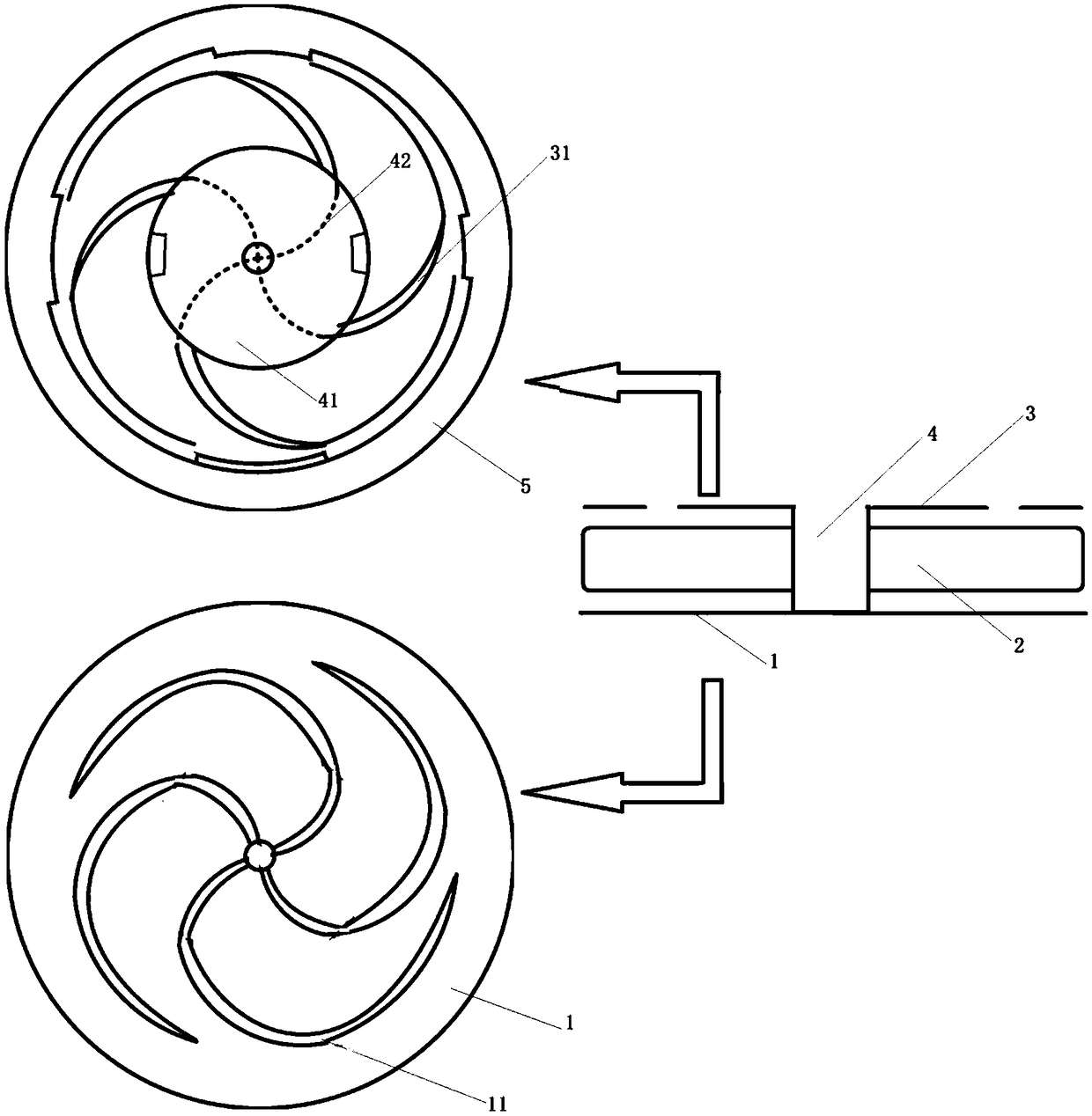
[0025] figure 1 It is a structure diagram of a microstrip patch antenna with a helical structure according to the present invention, such as figure 1 As shown, the microstrip patch antenna with a spiral structure of the present invention includes a stacked metal ground 1, a substrate 2 and a metal radiation layer 3. It is characterized in that the metal radiation layer 3 includes a feed structure 4 and at least two mutual A nested helical structure 31, the helical structure is metal, and the center of the helical structure converges on the feed structure;

[0026] The metal ground 1 includes at least two spiral notches 11 nested with each other, centered symmetrica...


PUM


Abstract

A microstrip patch antenna with spiral structures comprises a metal ground, a substrate and a metal radiation layer that are stacked, wherein the metal radiation layer comprises a feed structure and at least two spiral structures that are nested with each other and made of metal materials, the centers of the spiral structures converge on the feed structure, and the metal ground is further providedwith spiral notches that are nested with each other and take the center of the feed structure as the symmetric center. According to the microstrip patch antenna with the spiral structures disclosed by the invention, by adjusting the sizes of the upper and lower layers of spiral structures, including the width of each spiral structure, and the diameters, thread pitch, angular relationship and thelike of rotating structures, antenna parameters can be subjected to wide-band impedance matching. Therefore, no additional matching structure is required, and the structure itself has high consistencyand is easy to process. Moreover, due to the compression of the electrical length performed by the spiral structures, the electromagnetic signal transmission and reception in a wider spectral range can be realized by using a smaller antenna structure.

Description

technical field [0001] The invention relates to the communication field, in particular to a microstrip patch antenna with a helical structure. Background technique [0002] The existing microstrip patch antenna, by virtue of its planar structure, can be designed with a smaller profile, smaller size, and convenient integrated design structure, and its application ratio in various communication systems is gradually increasing. However, due to the limitations of its structure, the performance of traditional microstrip antennas is not satisfactory in terms of gain, directivity, surface wave, bandwidth and other performance. [0003] In view of the above defects, the existing technology usually adopts the loading coupling cavity to realize the miniaturization of the antenna; by adding matching resistance and reactance at the appropriate position of the antenna, the current distribution of the antenna is improved, and the matching of the resonant frequency is realized. However, n...

Claims


Application Information

Patent Timeline
IPC IPC(8): H01Q1/38H01Q1/48H01Q1/50
CPCH01Q1/38H01Q1/48H01Q1/50
Inventor 李明纵榜峰
Owner 宿州学院
Learn More