Optical cable assembly

An optical cable and component technology, applied in cable accessories, cable terminals, electrical components, etc., can solve the problems of easy water seepage, large optical fiber insertion loss value, poor salt spray resistance, etc., to improve waterproof sealing performance and meet the welding process. requirements, the effect of relieving cable stress

Pending Publication Date: 2018-11-23
PEACEFUL VISION ELECTRONICS LIANYUNGANG
View PDF0 Cites 1 Cited by
  • Summary
  • Abstract
  • Description
  • Claims
  • Application Information

AI Technical Summary

Problems solved by technology

[0004] Aiming at the above-mentioned shortcomings existing in the prior art, the present invention provides an optical cable assembly, which can effectively overcome the problems existing in the prior art that the opti

Method used


Image

  • Optical cable assembly
  • Optical cable assembly
  • Optical cable assembly

Examples


Embodiment Construction

[0021] In order to make the purpose, technical solutions and advantages of the embodiments of the present invention more clear, the technical solutions in the embodiments of the present invention will be clearly and completely described below in conjunction with the drawings in the embodiments of the present invention. Apparently, the described embodiments are some, but not all, embodiments of the present invention. Based on the embodiments of the present invention, all other embodiments obtained by persons of ordinary skill in the art without creative efforts fall within the protection scope of the present invention.

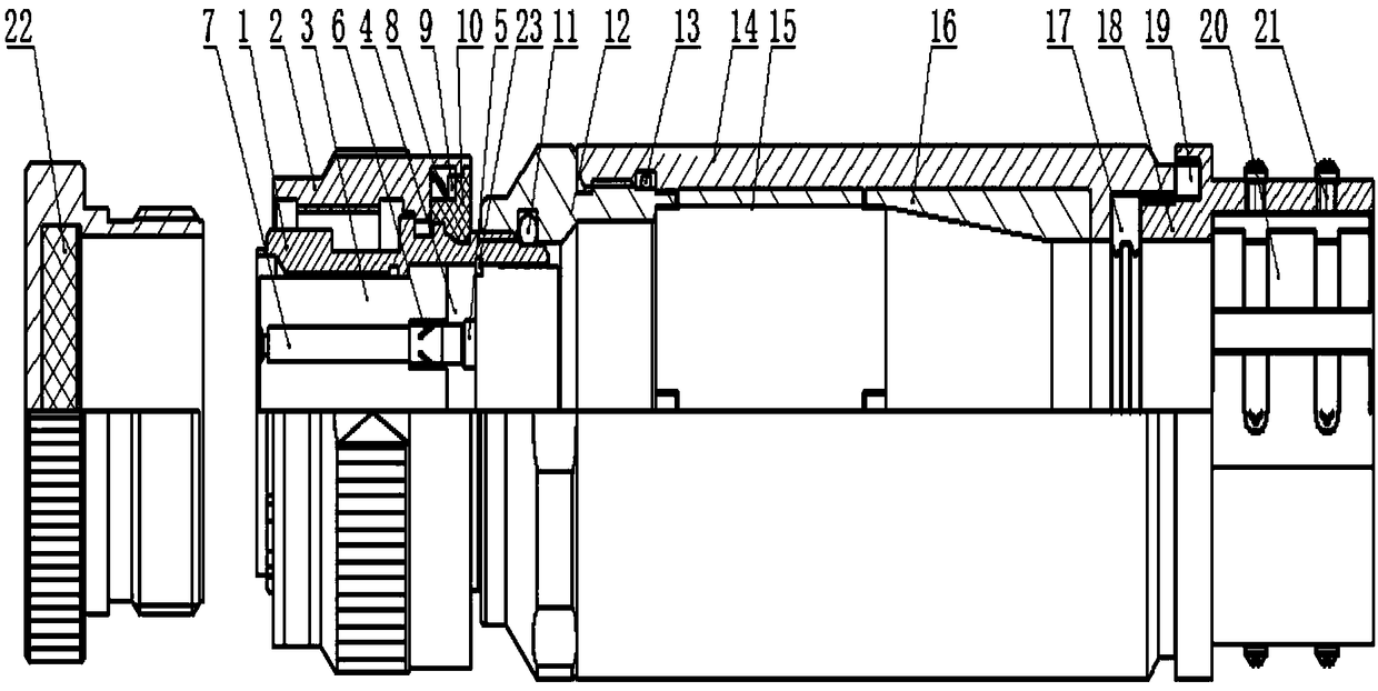
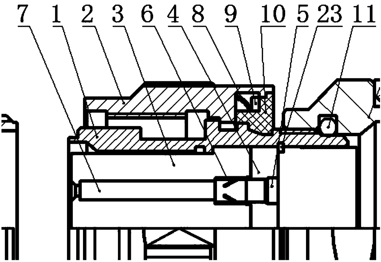
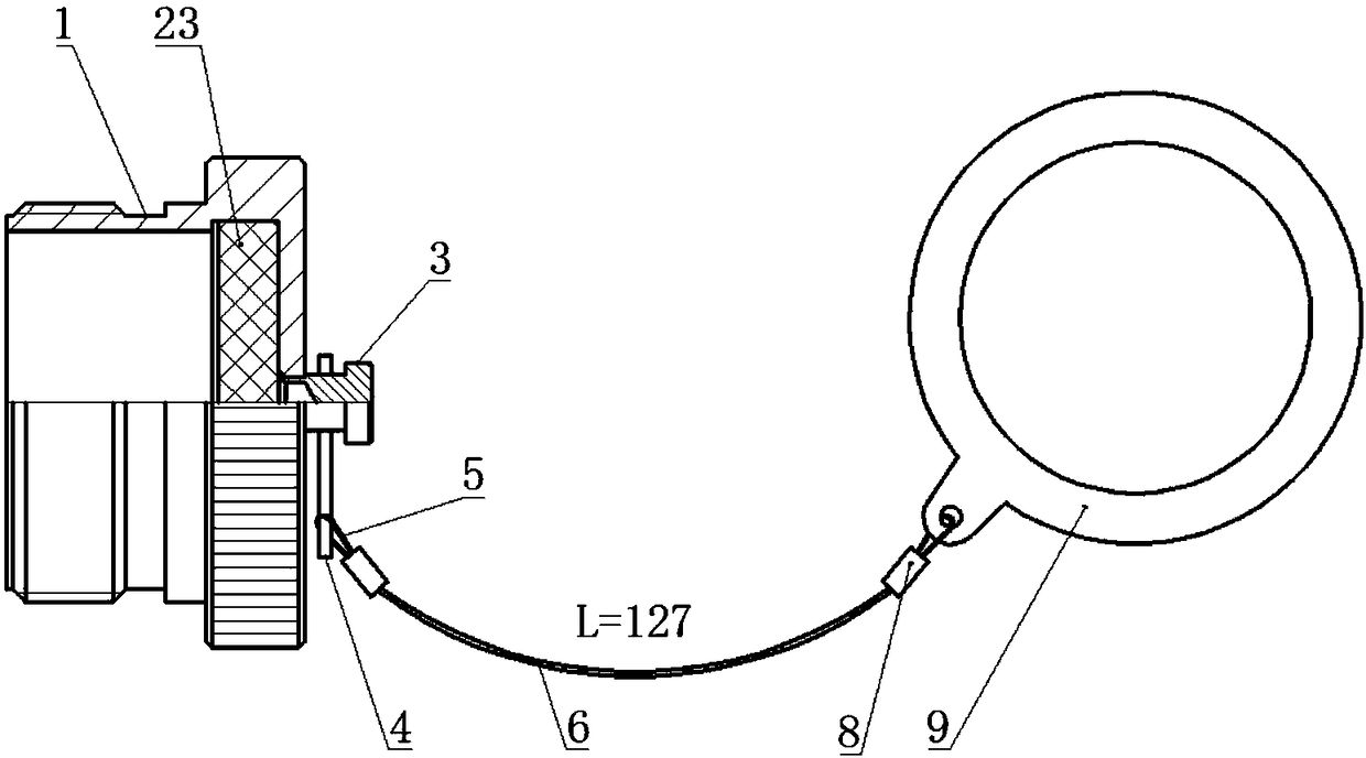
[0022] An optical cable assembly such as Figure 1-3 As shown, the head shell 1 is included, the right side of the head shell 1 is screwed with a metal head protection cap 22, the inner wall of the head shell 1 is provided with an insulator 3, and the center of the inner cavity of the insulator 3 is horizontally provided with a sheath 7. The right side of the ...


PUM

PropertyMeasurementUnit
Thicknessaaaaaaaaaa

Abstract

The invention relates to the technical field of optical cables, in particular to an optical cable assembly. The optical cable assembly comprises a head shell; the right side of the head shell is in threaded connection with a metal head protection cap; an insulator is arranged on the inner wall of the head shell; a sheath is transversely arranged in the center of an inner cavity of the insulator; apositioning claw is arranged on the right side of the sheath; an insulator cover plate is arranged on the right side of the positioning claw, and the right end of the positioning claw penetrates through and extends to the inner cavity of the insulator cover plate; an inserting hole assembly is arranged on the right side of the inner cavity of the insulator cover plate; the left side of the inserting hole assembly is connected with the right end of the positioning claw; a clamp spring is arranged on the top of the right side of the insulator cover plate; a locking sleeve is arranged on the outer wall of the head shell; and a stop clamping ring is arranged between the right side of the bottom of the locking sleeve and the right side of the top of the head shell. By virtue of the optical cable assembly disclosed by the invention, the problem that water seepage is easily caused in the using process of the optical cable assembly, salt fog resistance is poor, and the insertion loss value between the optical fibers after the product head base is plugged in is over high in the prior art can be effectively overcome.

Description

technical field [0001] The invention relates to the technical field of optical cables, in particular to an optical cable assembly. Background technique [0002] The products in the old state will experience water seepage during use, poor salt spray resistance, and the insertion loss between the optical fibers after the product head is mated is too large. Facing the technical requirements of general-purpose optical cable assemblies for naval electronic equipment, and implementing independent and controllable technical approaches, it is urgent to carry out the research and development of optical cable assemblies. Component products have better performance in terms of quality assurance such as optical fiber transmission performance, anti-salt spray, anti-mold ("three defenses"), waterproof sealing, anti-electromagnetic interference shielding performance, etc., and can be used in sonar equipment, optical transceivers, missiles, torpedoes The electrical connection and signal tra...

Claims


Application Information

Patent Timeline
IPC IPC(8): H02G15/04
CPCH02G15/043Y02A30/00
Inventor 王振海张瑞常鑫陈国栋
Owner PEACEFUL VISION ELECTRONICS LIANYUNGANG
Why Eureka
Try Eureka