Voltage source converter with ice melting function, and control method

A technology of a voltage source converter and a control method, which is applied in the direction of output power conversion device, conversion of AC power input to AC power output, electrical components, etc., and can solve the problem of limited operating range of DC voltage, increased device efficiency and cost, Affect the normal and safe operation of overhead lines and other issues, achieve the effect of realizing the operating range of DC voltage, reducing the risk of starting, and improving the utilization rate of equipment

Inactive Publication Date: 2018-11-23
NR ELECTRIC CO LTD +1
View PDF7 Cites 1 Cited by
  • Summary
  • Abstract
  • Description
  • Claims
  • Application Information

AI Technical Summary

Problems solved by technology

Therefore, icing is a freezing phenomenon that occurs under specific meteorological conditions. If a large area of ​​icing is formed on the overhead conductors, it will cause the tower to topple, and the conductors will be ice-covered and dance or break, which will directly affect the normal and safe operation of the overhead lines.
At present, the existing ice-melting solutions all need to add additional ice-melting equipment, which will increase additional investment, increase the space occupied by the equipment, and increase the complexity of the system.
In the prior art, there is also a scheme of voltage source converter and ice melting, but in the existing scheme, the operating range of DC voltage in the voltage source converter is limited, and because the voltage source converter has a rectifier bridge composed of diodes, it cannot output Low voltage, unable to meet the needs of ice melting; there are also plans to add a chopper circuit in the rear stage of the voltage source converter, although it can improve a certain operating range, but the efficiency and cost of the device are greatly increased

Method used


Image

  • Voltage source converter with ice melting function, and control method
  • Voltage source converter with ice melting function, and control method

Examples


Embodiment Construction

[0045] The present invention will be further described below in conjunction with accompanying drawing.

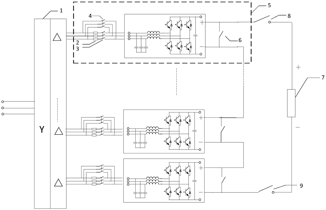
[0046] Such as figure 1 As shown, a voltage source converter with ice-melting function, the converter includes a multi-winding transformer and N converter modules, N≥2, the multi-winding transformer includes a primary winding and N secondary windings, the AC side of the converter module is connected to the secondary winding one by one, the DC side of the converter module is connected in series in sequence, the positive pole of the first converter module is used as the positive pole of the voltage source converter, The negative pole of the first converter module is connected to the positive pole of the second converter module, and so on, and the negative pole of the Nth converter module is used as the negative pole of the voltage source converter;

[0047] Wherein the converter module includes a first switch, a second switch, a resistor, a filter and an AC / DC converter, whe...


PUM


Abstract

The invention discloses a voltage source converter with an ice melting function. The converter comprises a multi-winding transformer and N converter modules, wherein N is larger than or equal to 2; the multi-winding transformer comprises a primary winding and N secondary windings; the alternating-current sides of the converter modules are connected with the secondary windings in a one-to-one correspondence mode, and the direct-current sides of the converter modules are cascaded to form a direct current bus; and each converter module comprises a first switch, a second switch, a resistor, a filter and an alternating current-direct current converter. The invention further discloses a corresponding control method of the voltage source converter. According to the control method for adjusting alternating-current and direct-current converters through switch switching, the ice melting function and the reactive compensation function of the voltage source converter can be realized; and the problem that the direct-current voltage adjusting range of the voltage source current converter is too narrow is solved through hierarchical starting, extra equipment does not need to be added, the reliability is high, and the cost performance is high.

Description

technical field [0001] The invention belongs to the technical field of high-power electric power electronic conversion, and in particular relates to a voltage source converter with the function of melting ice and a control method. Background technique [0002] In winter, due to the joint effect of air temperature, air humidity and wind speed, there is an icing phenomenon in which ice is formed from liquid water. Therefore, icing is a freezing phenomenon that occurs under specific meteorological conditions. If a large area of ​​icing is formed on the overhead conductors, it will cause the tower to topple, and the conductors will be iced and dance or break, which will directly affect the normal and safe operation of the overhead lines. At present, the existing ice melting solutions all need to add additional ice melting equipment, which will increase additional investment, increase the space occupied by the equipment, and increase the complexity of the system. In the prior ar...

Claims


Application Information

Patent Timeline
Patent Type & Authority Applications(China)
IPC IPC(8): H02M5/458H02G7/16
CPCH02G7/16H02M5/458H02M1/009
Inventor 王宇谢晔源刘洪德朱铭炼盛晓东田杰汪大全
Owner NR ELECTRIC CO LTD
Why Eureka
Try Eureka