Piezoelectric automobile loudspeaker

A speaker and car technology, applied in piezoelectric/electrostrictive transducers, sensors, electrical components, etc., can solve problems such as poor low-frequency response, capacitive loads, etc., to reduce energy consumption, reduce driving voltage, The effect of reducing the frequency

Active Publication Date: 2018-11-23
西安创联电气科技(集团)有限责任公司
View PDF5 Cites 1 Cited by
  • Summary
  • Abstract
  • Description
  • Claims
  • Application Information

AI Technical Summary

Problems solved by technology

Compared with traditional electro-acoustic devices, piezoelectric speakers have an ultra-thin shape, require a small sound cavity, and have the advantages of good heat dissipation, long life, no magnetic field, and electromagnetic radiation; however, there are no magnet materials, and high voltage can only be driven; low frequency response Not very good, problems with capacitive loads etc.
At present, the buzzer on the car is a piezoelectric buzzer. Due to the problems of the piezoelectric speaker, the piezoelectric speaker has not yet been applied to the car speaker on a large scale.

Method used


Image

  • Piezoelectric automobile loudspeaker
  • Piezoelectric automobile loudspeaker
  • Piezoelectric automobile loudspeaker

Examples


Embodiment 1

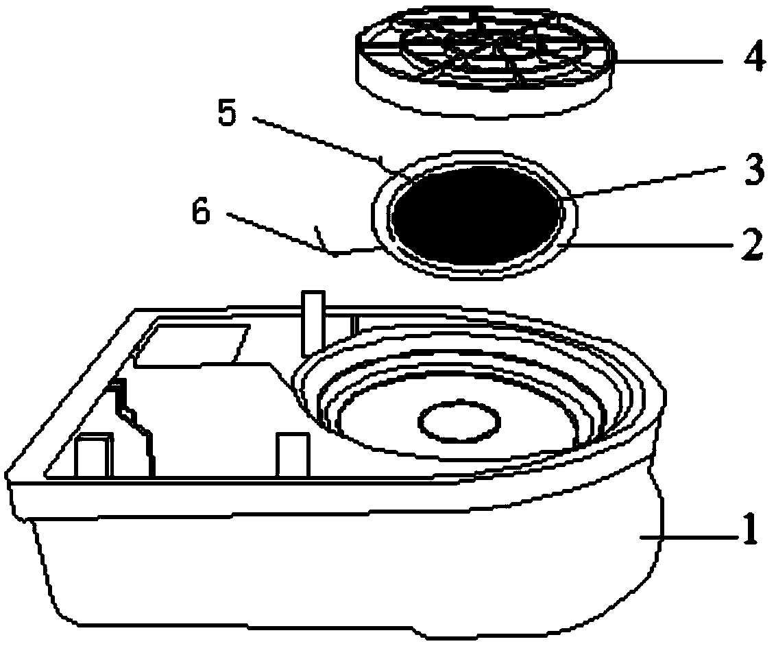
[0035] exist figure 1 Among them, the piezoelectric car speaker in this embodiment is composed of a casing 1 , a diaphragm 2 , a multilayer piezoelectric ceramic sheet 3 , a protective cover 4 , a first lead 5 , and a second lead 6 connected together.

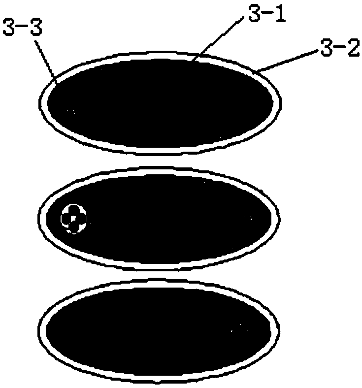
[0036] A sounding unit is installed in the sound chamber of the shell 1, and a protective cover 4 is installed on the shell 1 above the sounding unit. The structure of the sounding unit is that the upper surface of the diaphragm 2 is pasted with a multi-layer piezoelectric ceramic sheet 3. The electric ceramic sheet 3 is connected with a first lead wire 5, and the diaphragm 2 is connected with a second lead wire 6. The diaphragm 2 is a round solid brass sheet, or a round solid stainless steel sheet, or a round solid poly Vinyl chloride tablets, such as image 3 , the multilayer piezoelectric ceramic sheet 3 is cylindrical, the cross-sectional area of ​​the diaphragm is 2.5 times the cross-sectional area of ​​the multilayer pie...

Embodiment 2

[0049] In this embodiment, a sounding unit 2 is installed in the acoustic cavity of the casing 1, and a protective cover 3 is installed on the casing 1 above the sounding unit 2. The structure of the sounding unit 2 is that the upper surface of the diaphragm 2 is pasted with a multi-layer The piezoelectric ceramic sheet 3 is connected with the first lead wire 5 on the multilayer piezoelectric ceramic sheet 3, and the second lead wire 6 is connected on the vibrating membrane 2, and the vibrating membrane 2 is a circular sheet processed with an annular hole to divide the circular sheet into outer parts. The annular sheet and the inner circular sheet, the outer annular sheet and the inner circular sheet are connected by reinforcing ribs evenly distributed along the circumferential direction, such as Figure 4 , the material of the vibrating membrane 2 is a brass sheet, or a stainless steel sheet, or a polyvinyl chloride sheet, the multilayer piezoelectric ceramic sheet 3 is cylind...

Embodiment 3

[0052] In this embodiment, a sounding unit 2 is installed in the acoustic cavity of the casing 1, and a protective cover 3 is installed on the casing 1 above the sounding unit 2. The structure of the sounding unit 2 is that the upper surface of the diaphragm 2 is pasted with a multi-layer Piezoelectric ceramic sheet 3, the multilayer piezoelectric ceramic sheet 3 is connected with the first lead wire 5, and the diaphragm 2 is connected with the second lead wire 6, and the diaphragm 2 is a square solid brass sheet, or a square solid stainless steel sheet , can also be a square solid polyvinyl chloride sheet, such as Figure 5 , the multilayer piezoelectric ceramic sheet 3 is cylindrical, and the cross-sectional area of ​​the diaphragm is 2.5 times the cross-sectional area of ​​the multilayer piezoelectric ceramic sheet. Other components and the connection relationship of the components are the same as in Embodiment 1.

[0053] The preparation method of the multilayer piezoelec...


PUM


Abstract

The invention discloses a piezoelectric automobile loudspeaker. The interior of a vocal cavity of a housing is provided with a sound generating unit, and the housing above the sound generating unit isprovided with a protection cover in a matched manner. The sound generating unit is formed by multiple piezoelectric ceramic pieces pasted on the upper surface of a conductive vibrating diaphragm. Thestructure of multiple piezoelectric ceramic pieces is formed by the alternate stacking of big electrode layers and piezoelectric ceramic layers, wherein the upper and lower surfaces of the piezoelectric ceramic pieces are big electrode layers. The piezoelectric ceramic layers are provided with metalized microholes, and the interiors of the metalized microholes are provided with small electrodes which enable the big electrode layers located at upper and lower sides of the piezoelectric ceramic layers to be connected. The piezoelectric ceramic layers are connected with first lead wires, and thevibrating diaphragm is connected with a second wire.

Description

technical field [0001] The invention belongs to the technical field of acoustic-electric conversion, and in particular relates to a piezoelectric automobile loudspeaker. Background technique [0002] Piezoelectric speakers or piezoelectric buzzers are devices that use the inverse piezoelectric effect to produce sound. When the electrodes on the piezoelectric ceramic sheet are connected to a voltage signal, the ceramic sheet will be stretched and deformed, and the ceramic sheet and the diaphragm will be bonded together. , The ceramic disc drives the diaphragm to vibrate, and then pushes the air to vibrate to generate sound pressure and emit sound. Compared with traditional electro-acoustic devices, piezoelectric speakers have an ultra-thin shape, require a small sound cavity, and have the advantages of good heat dissipation, long life, no magnetic field, and electromagnetic radiation; however, there are no magnet materials, and high voltage can only be driven; low frequency r...

Claims


Application Information

Patent Timeline
Patent Type & Authority Applications(China)
IPC IPC(8): H04R17/00
CPCH04R17/00
Inventor 孙卫龙梁雪皇晓辉朱颖贺立龙殷春民
Owner 西安创联电气科技(集团)有限责任公司
Why Eureka
Try Eureka